
User's Manual
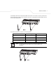
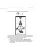
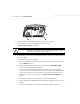
Table Of Contents

AP-5131 Access Point: Installation Guide
12
3. Attach the Radio 1 and/or Radio 2 antennas to their correct connectors.
For information on the antennas available to the AP-5131, see
“
AP-5131 Antenna Options” on page 6.
4. Cable the AP-5131 using either the Symbol Power Injector solution or an approved line cord
and power supply.
For Symbol Power Injector installations:
a. Connect a RJ-45 Ethernet cable between the network data supply (host) and the Power
Injector Data In connector.
b. Connect a RJ-45 Ethernet cable between the Power Injector Data & Power Out
connector and the Symbol AP-5131 LAN port.
c. Ensure the cable length from the Ethernet source (host) to the Power Injector and
AP-5131 does not exceed 100 meters (333 ft). The Power Injector has no On/Off power
switch. The Power Injector receives power as soon as AC power is applied. For more
information on using the Power Injector, see “
Symbol Power Injector System” on
page 8.
For standard power adapter (non Power Injector) and line cord installations:
a. Connect RJ-45 Ethernet cable between the network data supply (host) and the AP-5131
LAN port.
b. Verify the power adapter is correctly rated according the country of operation.
CAUTION Ensure you are placing the antennae on the correct connectors
(depending on your single or dual-radio model and frequency used) to
ensure the successful operation of the AP-5131.
!