
User's Manual
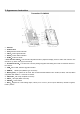


The description of LED status indicator
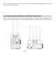
4. OLED Display
Boot Screen Main Screen
(When Tx and Rx both have no signal connection, (When Tx and Rx have normal signal connection,
Tx and Rx display the same. Fig.1) Tx and Rx display the same. Fig.2)
Remark: Channel switch is adjusted up or down by the red five-direction adjustment button under OLED, 7
wireless channels in total.
Switch Screen
a : (Transmitter : Push the red five-direction adjustment key at the bottom of the display screen. Fig 3 and Fig 5)
b : (Receiver : Push the red five-direction adjustment key at the bottom of the display screen . Fig 4 and Fig 5)
Remark:
1. The transmitter and receiver display different contents in the configuration setting interface: the transmitter only
displays "PAIR", and the receiver displays "CONF", "PAIR" (Fig 3 , Fig 4).
2. In one transmitter to one receiver mode, receiver setting is ‘”HOST” mode. In one transmitter to multi-receivers
mode, one receiver setting is “HOST” mode, other receivers are all been set in “SLAV” mode. In one transmitter to
multi-receivers mode, the “HOST” mode receiver must be on.
3. The setting default options of receiver “CONF” is “HOST”. To set the "HOST" mode, push the five- direction
switch up and down, select "HOST" and press the five- direction switch. At the bottom of the screen, "PLEASE
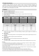
Device LED indicator Status Description
FLOW2000
Receiver
Power
Constant On Power connected and switched on
Off Power disconnected and switched off
Video
Constant On There is recognizable video signal input
Flash There is no recognizable video signal input
Link
Constant On The wireless network connection is normal
Flash The wireless network connection is abnormal
Signal source
Signal format
Fre
q
uenc
y
switch
Signal strength
Fig.1
Fig.2
No signal
Autochannelmode
Signal strength
Fig.3 Fig.4
Pair
Configuration
Host
Slave
Pair
Firmware
Fig.5