
User's Manual


ITC2100-NA Operation and Service Manual Version 1.0
© SWISSPHONE Wireless AG
Page 58 of 129
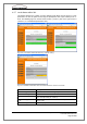
Digital inputs
Here the names for the input contacts can be entered. Afterwards these names are dis-
played in the status menu (see Status -> Digital I/O channels). Channel 5 is located on the
D-Sub 9 -connector of the sync card SC (pin 7 and 9). Channel 6 and 7 are located on the
digital I/O-card.
Fig. 6-24: Configuration of the digital inputs without (l.) / with I/O card (r.)
Digital outputs
Here the names for the output contacts can be entered. Afterwards these names are dis-
played in the status menu (see Status -> Digital I/O channels). The contact can be opened
or closed locally by selecting "On" or "Off" and afterwards clicking the Apply button. Chan-
nel 1 is located on the D-Sub 9 connector of the sync card SC (pin 6 and 8). Channel 2 to 8
are located on the digital I/O card. If "On" is selected in the field Siren steering this is dis-
played for channels 1 to 3.
Fig. 6-25: Configuration of the digital outputs without (l.) / with I/O card (r.)