
User's Manual


ITC2100-NA Operation and Service Manual Version 1.0
© SWISSPHONE Wireless AG
Page 57 of 129
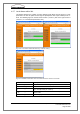
Fig. 6-22: Activation of the version I or II (Value I, Value II)
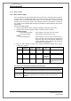
The inputs and outputs can be configured by clicking the Configuration button in the field
Digital I/O card. A selection between "Local alarming", "Digital inputs" and "Digital outputs"
can be made in the field Function.
Local alarming
Here a selection can be made whether a POCSAG pager message is to be transmitted on
the leading or trailing edge of an input signal. The corresponding POCSAG message and
also the RIC with subaddress can be defined in the fields Channel local alarming 1, Chan-
nel local alarming 2, etc. Channel local alarming 1 is located on the D-sub 9 plug of the
sync card (Pin 1 and 4). Channel local alarming 2 to 4 are located on the digital I/O card.
Fig. 6-23: Configuration of the local alarming without (l.) / with I/O card (r.)