
User's Manual


ITC2100-NA Operation and Service Manual Version 1.0
© SWISSPHONE Wireless AG
Page 56 of 129
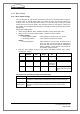
Note: The I/O card can only be used starting with the following versions:
ITC2100
SW state:
≥ V 2.00
(see System -> Information about… ->
ITC2100 BOS)
Sync
card
State Tx-FPGA:
> 1.6
(see System -> Information about… -> Appli-
cations)
HW state:
≥ Index D0
(Connector ST101 fitted)
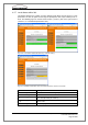
Fig. 6-21: Numbering and designation of pins on the I/O card and sync card
Configuration of the inputs and outputs:
The ITC2100 - Version I ("value I") has 2 optocouped inputs (1 alarm input + 1 input for re-
mote polling) and 1 optocoupled output. These cannot be used for activating sirens.
The ITC2100 - Version II ("value II") has 7 optocoupled inputs (4 alarm inputs + 3 outputs
for remoto polling) and 8 rely outputs. These can be used for activated sirens.
Select "enabled" in the field Value "Value I" or "Value II" and afterwards in the Digital I/O
card. To configure siren actuation select "enabled" in the field Siren support.
I/O card:
Sync card: