
User's Manual


ITC2100-NA Operation and Service Manual Version 1.0
© SWISSPHONE Wireless AG
Page 49 of 129
6.5.6 Digital IO channels
On the configuration stage II version, the individual statuses of the I/O channels are dis-
played at this point. The inputs and outputs can be displayed using a drop-down menu..
Depending on the selected version "Value I" or "Value II" more or less one or two inputs or
outputs are displayed, as shown in the following figures, on the left "Value I" (without I/O
card), on the right "Value II" (with I/O card).
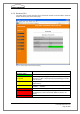
6.5.6.1 Digital Inputs
Fig. 6-13: Status page of the digital inputs without (l.) / with I/O card (r.)
Field
(Digital inputs)
Description
Channel 1..4: Local
alarming
Alarm inputs (local alarming)
Indicates the status of the alarm inputs 1 to 4 or whether the
corresponding input is active or inactive. A predefined
POCSAG message (see chapter 6.6.1.2) can be transmitted
over these inputs (e.g. via the triggering of a fire detector).
Channel 5..7: InputLabel-
5..7
Inputs for remote inquiry (digital inputs)
Indicates the status of the digital alarm inputs (on, off). This
information can be requested by a remote network alarm con-
troller (e.g. the status of an active lightning protector) In the
configuration menu the input displayed here can be given a
name, like for instance "Lightning protection".
State alarming
The operating mode of the digital I/O module is displayed. The
mode can be active, non active or faulty.