
User's Manual


ITC2100-NA Operation and Service Manual Version 1.0
© SWISSPHONE Wireless AG
Page 46 of 129
6.5.5 Hardware Components
Optional modules, such as I/O card or the GPS interface card, can also be inserted in the
ITC2100-NA. The GSM module (remote maintenance) is not yet implemented and therefore
deactivated
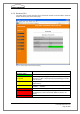
The figure on the left below displays the hardware components in a Master ITC, a Standby
ITC and a Slave ITC and the figure on the right below displays the hardware components of
a Multimaster ITC (in the menu "Configuration" under the link "Optional base station set-
tings", the field "GPS receiver" is set to "enabled").
Fig. 6-12: Status pages of the hardware components in case of master (l.) and multi-master ITC (r.)
Field:
Hardware State
Description
Hardware ready!
All HW componenten are ready for operation.
Hardware disabled!
None of the HW components quoted are enabled
Error in hardware!
One or more HW components is faulty. Each faulty
HW components is displayed in its corresponding
component field.
Field:
Sync state
Description
Ok
Synchronous transmission between Masters is possi-
ble. The GSM time pulse (time reference signal) is
being received regularly.
Timer in freerun
The GPS time pulse (time reference signal) is no
longer being received. The Master's synchronisation is
guaranteed via the current internal quartz time correc-
tion factor.
Timer high
The GPS time pulse (time reference signal) has not
been received for 30 min. The Master's synchronisa-
tion is guaranteed via the current internal quartz time
correction factor for a further 30 min (total 60 min.).
Timer exceeded
The GPS time pulse (time reference signal) has not
been received for 60 min. The Master's synchronisa-
tion is no longer guaranteed and the corrected quartz
time is not precise enough.