
User's Manual


ITC2100-NA Operation and Service Manual Version 1.0
© SWISSPHONE Wireless AG
Page 18 of 129
Step 3) Field installation
When the ITC is used as Master ITC:
1. Connect a high grade LAN cable (min. Cat5) to the RJ45 Ethernet interface of
the controller for ITC and network control.
2. Connect a GPS antenna to the GPS interface card, when the ITC is to be used
as a Master ITC (see chapter 6.6)
Make a connection (communication):
3. Connect the input/output lines to the sync card or to the optional I/O card (see
chapter 6.4 oder 6.7).
4. When a local redundant network alarm controller is to be used, connect it to the
controller's serial interface (communication protocol MIP11+)
5. Connect the transmitter/receiver antenna coaxial cable (see chapter 5.12).
Make power connections:
6. Connect the fully-charged battery 5.10).
7. Connect any external device whose power is to be provided by the ITC (see
chapter 5.11).
8. Connect the mains cable (ITC main switch off: position 0).
9. Switch the ITC on (mains button set to position 1).
Carry out the setting of the ITC end configuration in the service web interface.
Step 4) Functional test
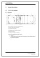
10. The green LED's on the PS 200W, RC and SC card, must all light.
If the red LED on the power unit flashes, check the battery fuse. First
switch off the mains switch, check the battery fuse and, if necessary, re-
place it.
If the yellow LED on the power unit lights, the battery has insufficient power
and must be recharged.
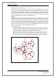
11. Check the status indicators in the ITC service web interface. On the status
page, no other field should be red except for the field Receiver (Rx). This field
changes it status to green as soon as the ITC is active in the network and it re-
ceives messages having sufficient field strength from a neighbouring ITC.
12. Transmit a test message to a local pager or a neighbouring ITC.
Warning:
Incorrect handling of the base station may lead to injury or damage to the system