
User's Manual


ITC2100-NA Operation and Service Manual Version 1.0
© SWISSPHONE Wireless AG
Page 125 of 129
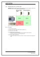
Fig. 8-8: Cabling of the RC or RC09 card
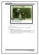
Insert the new RC or RC09 card into its slot and tighten the 2 screws on the front
panel
6) Connect the mains cable
7) Switch on the ITC2100 (mains switch to position "1"), the ITC2100 will boot
8) Function control:
Green LED of the RC or RC09 card is on
In the status page in link "Receiver (RX)" the first three fields "Frequency Prog.
(I2C-Bus):", "Frequency Prog. (PLL):" and "PLL Frequency:" show OK.
Only for RC card: In the system page in link "Information about...Applications" the
field "Rx-FPGA:" shows the value of min. 0.8.
a) Cable to transceiver module TRx
b) Version of the Rx-FPGA (V 0.8)
c) Version of the hardware (index D)