
User's Manual


ITC2100-NA Operation and Service Manual Version 1.0
© SWISSPHONE Wireless AG
Page 116 of 129
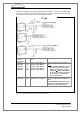
All inputs are equipped as indicated in the following description. A connection variation on
the relay outputs permits the I/O card's 13.8V supply to be used to operate an external cir-
cuit. A maximum of 10A can be supplied. The maximum cross-section of the connection
wires is1mm
2
.
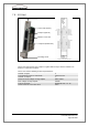
Fig. 7-14: Pin connections for the Optocoupler inputs of the I/O card
Relais Pin
Bridge no. for
VCC (as standard
not fitted)
Relais 0*
BR153
Relais 1*
BR150
Relais 2*
BR154
Relais 3*
BR151
Relais 4*
BR152
Relais 5*
BR155
Relais 6*
BR158
Designation
in service
web interface
Pins
Connection at I/O card (out-
puts):
Description:
Channel 2
Channel 3
Channel 4
Channel 5
Channel 6
Channel 7
Channel 8
1 / 2
3 / 4
5 / 6
7 / 8
9 / 10
11/12
13/14
Relais 0 / Relais 0*:
Relais 1 / Relais 1*:
Relais 2 / Relais 2*:
Relais 3 / Relais 3*:
Relais 4 / Relais 4*:
Relais 5 / Relais 5*:
Relais 6 / Relais 6*:
Potential-free outputs. As standard
BR15x is not fitted.
Note:
If VCC 13.8V is used for external
circuits (BR15x fitted), the output
is no longer potential-free.
Channel 8
14/15
Relais 6* / GND or Open 6:
As standard no function, i.e. pin 1 and
10 are open, BR181 and BR185 are not
fitted. If BR18/1 BR185 are fitted pins
1/10 are connected to VCC (13.8V) and
are therefore no longer potential-free