
User's Manual


ITC2100-NA Operation and Service Manual Version 1.0
© SWISSPHONE Wireless AG
Page 113 of 129
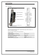
7.7.3 Connector Pin Assignment of GPS Antenna and S-Com Card
The cable used for connecting the GPS receiver to the Master ITC's has the following pin
connections:
GPS antenna:
Pin layout seen from solder side
Connector: IEC 60130-9 (female)
S-Com card (Com 4):
Pin layout seen from solder side
Connector: D-Sub9 (female)
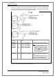
GPS receiver pin connections
Pin designation
S-Com card (Com 4) pin connec-
tions
1
TP-
4
2
Rx-
3
3
Rx+
7
4
Tx-
2
5
Tx+
6
6
+12V
1
7
GND
5
8
TP+
8
--
9
TP±: Time pulse (time reference) line for synchronisation
Rx±/Tx±: Communication line
+12V: Supply
GND: Earth
Fig. 7-11: Pin connections for the GPS antenna and S-Com card
Rx-
Tx-
TP-
GND
Tx+
Rx+
TP+
+12V
+12V Tx- Rx- TP- GND
Tx+ Rx+ TP+