
User's Manual


ITC2100-NA Operation and Service Manual Version 1.0
© SWISSPHONE Wireless AG
Page 111 of 129
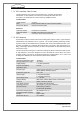
7.7 GPS Interface Card (S-Com) and GPS Antenna
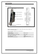
Fig. 7-9: GPS interface card (S-Com) and GPS antenna
In order to permit as much flexibility as possible when determining the location of the GPS
antenna, it is equipped with an RS422/RS485 interface that has a 200 meter long cable.The
time pulse is fed over a differential cable of a similar length. For the supply over such a dis-
tance with a supply of 12V, the cable cross-sectional should be 0.25m
2
. All inputs and out-
puts to the GPS antenna are protected against surge voltages. An 8 pin IEC 60 130-9
connecror is used for connection to the unit.
The GPS antenna is connected to the S-Com card via the Com4 connector..
Note: To ensure adequate overvoltage protection the GPS antenna must be correctly
earthed (e.g connect the GPS antenna's aluminium housing to the building's earth). Moreo-
ver Swissphone recommends the connection of a series overvoltage protection to the GPS
interface card.
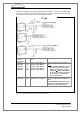
Fig. 7-10: GPS antenna connection to the S-Com-Karte
GPS Interface Card (S-Com)
GPS Antenna
Shielded connection cable: max. 200m
(COM 4)