
User's Manual


ITC2100-NA Operation and Service Manual Version 1.0
© SWISSPHONE Wireless AG
Page 107 of 129
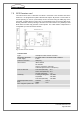
Fig. 7-6: Pin connections of the optocoupler inputs on the sync card
Designation
in service
web interfac
Pins
D-Sub9 connctor on
SC card
(inputs):
Description:
Channel 1
Channel 5
1 / 4
7 / 9
IN 0 / GND 0:
IN 1 / GND 1:
Galvanic isolated inputs, potential-free. As
standard resistors R43 and R47 are not fitted.
Note:
If R43 or R47 (0) is fitted, GND 0 (pin 1) or
GND 1 (pin 9) is connected to ITC chassis
and therefore no longer potential-free.
Input 0 (pins 1/4) is used as "Local Alarm"
Input 1 (pins 7/9) is used as "Digital input".