
User's Manual


ITC2100-NA Operation and Service Manual Version 1.0
© SWISSPHONE Wireless AG
Page 106 of 129
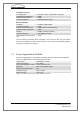
LED type
Description
Green LED (Power)
lights
The sync card is powered.
Orange LED (Transmit)
lights
Lights for as long as a message is being sent from the sync
card to the transceiver module.
Red LED (Status) lights
Lights when a status of the ITC is not OK (e.g. low forward
power, high reflection power, etc.)
Red LED (Status)
blinks
The battery voltage has fallen below the critical value and the
base station is switched to safety system status. (BSC runs
down individual processes).
All LED's blink briefly
The ITC is fully booted up.
All LED's light
The ITC has been shut down fully and can know be switched
off.
Table 4: Functional description of the SC card LEDs
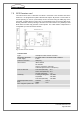
The sync card has 2 inputs and 1 output. Together with the I/O card this extends the sys-
tems inputs to 7 and outputs to 8.
The sync card's inputs and ouputs meet the following specifications:
Number of inputs:
2
Current/voltage range of the opto-inputs:
5-25mA, 5-15V
Number of outputs:
1
Maximum current/voltage at the opto-output:
25mA, 13.8V
Type of connector:
D-Sub9
Cross-section of connection wires:
1mm
2
Fig. 7-5: Pin connections of the optocoupler output to the sync card
Designation
in service
web interfac
Pins
D-Sub9 connector
onn SC card
(output):
Description:
Channel 1
6 / 8
Out 0 / GND:
Output with a voltage 13.8V. The resistor is
connected as standard, between pin 8 and ITC
chassis.