
User's Manual


ITC2100-NA Operation and Service Manual Version 1.0
© SWISSPHONE Wireless AG
Page 105 of 129
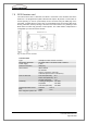
7.4 Sync Card (SC)
Fig. 7-4: Sync card (SC)
The sync card SC is responsible for forwarding the data time-synchronously to the transmit-
ter. In addition, the following functions are integrated in the sync module:
Sync pulse detection. A pulse for synchronisation of the data is transmitted by the RC
card via the AT96 bus.
Optocouplerr connection for the input/outut. Voltages beween 10V and 20V can be ap-
plied to the input.
The sync module essentially consists of a s counter and a buffer for the transmit data.
Standard components and FPGA logic have been used. The counter runs for 2
28
us (ap-
prox. 4.5 minutes) and then restarts at zero. It can be polled via a register from the BSC.
Various registers are available for setting start instants, stop instants and switchover refer-
ence instants. The transmit data memory has adequate capacity to allow at least one mi-
nute continuous transmission at 2400 bit/s per second. The sync module has Eurocard
format (3 HE) and is plugged onto the AT96 bus. The following sockets, keys and indicators
are located on the front panel:
LEDs (Power on, Transmit, Status)
Reset button: Resets all registers (but not the counter) and generates BSC interrupt
Shutdown button (large black button). When this button is pressed and held down for
longer then 7 seconds, , the ITC is shut down.
9 pole D-Sub interface (used as connection for the optocoupler!)
Green LED (Power)
Orange LED (Transmit)
Red LED (Status)
D-Sub9 interface; 2x input, 1x output
Shutdown button
Mounting screw
Mounting screw
Reset button (Reset)
AT96 interface