
User's Manual


Shockbursttm configuration word make NewMsg_RF24L01 rf24l01 to deal with RF protocol, after
configuration is complete, in the process of NewMsg_RF24L01 rf24l01, only need to change the
contents in the lowest one byte, the receiving and sending mode switch between.
ShockBurstTM configuration word can be divided into the following four parts:
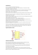
Data width: the number of data occupied in the radio frequency packet. This allows the
NewMsg_RF24L01 to distinguish between the received packet data and the CRC code;
Address width: the number of addresses in the radio frequency packet. This allows the
NewMsg_RF24L01 to distinguish between address and data;
Address: the address of the receiving data, the address of the channel 0 to the channel 5;
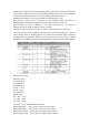
CRC: enable CRC to generate NewMsg_RF24L01 verification code and decoding. When using the
CRC technology within the NewMsg_RF24L01 chip, make sure that the CRC check is enabled in
the configuration word (EN_CRC CONFIG), and send and receive the same protocol. The bit
description of the CONFIG register of the NewMsg_RF24L01 configuration word is shown below.
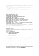
Reference source code
#include <reg51.h>
//<nRF24L01_Pins >
sbit MISO =P1^3;
sbit MOSI =P1^4;
sbit SCK =P1^5;
sbit CE =P1^6;
sbit CSN =P3^7;
sbit IRQ =P1^2;
sbit LED2 =P3^5;
sbit LED1 =P3^4;
sbit KEY1 =P3^0;
sbit KEY2 =P3^1; // SPI(nRF24L01) commands
#define READ_REG 0x00 // Define read command to register
#define WRITE_REG 0x20 // Define write command to register
#define RD_RX_PLOAD 0x61 // Define RX payload register address
#define WR_TX_PLOAD 0xA0 // Define TX payload register address