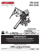
PB 8328 WS 8328 JAMBOREE IMPORTANT!! PLEASE READ BEFORE BEGINNING ASSEMBLY!! Please make sure all lumber, hardware and accessory parts are accounted for. If you are missing anything, please DO NOT RETURN to the store where purchased. Please call our Customer Service Department at the number below.
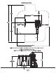
DIMENSIONS STRUCTURE.
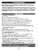
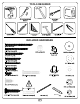
TOOLS REQUIRED DRILL HAMMER PHILLIPS BIT TAPE MEASURE PLIERS CARPENTER SQUARE INCLUDED HARDWARE Small Square Bit
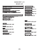
HARDWARE 2 7 1 12 1 4 2 4 1 3 1 Small 7
SA6066 BOX 1 of 2 BOARD LIST
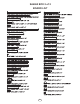
SA6065 BOX 2 of 2 BOARD LIST 9
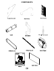
COMPONENTS
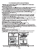
STEP 1 Flush Check to make sure structure is square Per Board NOTE HOLES PANEL A Install 30mm Screws With Heads Flushed To Board To Avoid Protrusions.
STEP 2 Per Board A LL A BO RD S Check to make sure structure is square Per Board FLUSH PANEL D Per Board Per Board FLUSH Install 30mm Screws With Heads Flushed To Board To Avoid Protrusions.
STEP 3 Check to make sure structure is square PANEL C Flush T-Nut Small Flush NOTE HOLES Flush to the bottom NOTE: HOLE ORIENTATION T-Nut Small Flush FRAME A Flush Note: Tap each T-Nut into its pre-drilled hole until the metal tangs sink fully into the wood.
STEP 4 FRAME A FLIP FRAME OVER
STEP 5 T-Nut Small per Board This Side NOTE HOLE Flush per Board This Side NOTE: HOLE ORIENTATION T-Nut Small Flush FRAME B Check to make sure structure is square WINDOW PANE INSTALL Note: Tap each T-Nut into its pre-drilled hole until the metal tangs sink fully into the wood.
STEP 6 FRAME B FLIP FRAME OVER
STEP 7 Flush 3’’ From Outside of Post PANEL A Flush Check to make sure structure is square 3’’ From outside of post To end of horizontal support.
STEP 8 FRAME A Flush Flush 3’’ From Outside of Post to End of Horizontal Support.
STEP 9 Flush per side Back of Tower Flush NOTE: PRE-DRILL HOLES GOING INTO DECK SUPPORTS per side 55-1/4’’ 11’’ 11’’ Top View of Tower
STEP 10 per board Flush Flush per joint Flush PANEL B PANEL B INSTALL
STEP 11 T-Nut Small 46-5/8’’
STEP 12 T-Nut Small HEADS FLUSH
STEP 13 Flush Flush Flush Flush Check to make sure structure is square Flush Flush TE NO ES L HO Flush 45 ’’ T O HO L 46-5/8’’ Flush E Flush PANEL E Flush FRAME C Flush Flush FLIP FRAME OVER
STEP 14 T-Nut Small LIFT FRAME UP Note: Tap each T-Nut into its pre-drilled hole until the metal tangs sink fully into the wood.
STEP 15 Check to make sure structure is square Flush FRAME C Flush
STEP 16 Check to make sure structure is square Flush per joint PANEL D Flush Inside View of Tower 77-1/4’’ Flush
STEP 17 Flush per board per board PRE-DRILL SUPPORTS Flush 12-3/4’’ 12-3/4’’ Top View of Terrace
STEP 18 Flush per board
STEP 19 Flush Flush 2-1/4’’ Flush
STEP 20 Flush 26’’
STEP 21 Loc Nut Attach Tower Beam Support Board as shown.
STEP 22 Swing Beam Large Hanger Beam Clamp 2 1 3 x4 Correct Orientation 4 Screws 5
STEP 23 A-Frame SB Support A-Frame Small Small A-Frame Support Small
STEP 24 Bracket x2 x2
STEP 25 Beam Brace Small Barrier Boards Removed for Clarity
STEP 26 Carriage Bolt Small Barrier Boards Removed for Clarity
STEP 27 Screws x2 CENTERED Screws x2 Screws Screws Front View Screws per board Screws Screws x2 NOTE: Overlap Shingles as shown.
STEP 28 TURN ROOF ASSEMBLY ON END.
STEP 29 Screws Screws Screws per board Screws Screws
STEP 30 ALIGN SCREWS WITH PRE DRILLS Flush Screws Per side Side View Top Screws per board Flush
STEP 31 Screws Flush Side View Bottom
STEP 32 Bolts
STEP 33 NOTE HOLES NOTE HOLES TABLE SUPPORT Top View of Table Inside View of Table
STEP 34 Flush Flush Check to make sure structure is square BOTH SIDES TABLE PRE-DRILL BOARDS WITH 1/8’’ DRILL BIT TO MINIMIZE SPLITTING BOTH SIDES Note: Pre-Drill boards with 1/8’’ drill bit as shown to prevent splitting.
STEP 35 Flush Make Certain This Side Has Holes Closest To The Edge.
STEP 36 per side
STEP 37 CENTERED per joint FLAP UP FLAP DOWN FLAP ON THE UNDERSIDE. FLAP ON TOP.
STEP 38 ATTACH SLIDE INTO Screws Slide Stake
STEP 39 Pan Screw
STEP 40 1 2 3 NOTE: Crimp swing hanger tightly closed Ring-Trap Combo Assembly Attach Quick Link to chain oriented as shown.
Swing Seat Assembly BOTTOM OF SEAT BOTTOM OF SEAT STEP 41
STEP 42 Carriage Bolt Spacer Loc Nut Steering Wheel Assembly 1. Choose a desired location for the Steering Wheel and drill a 5/16” diameter hole through the lumber. NOTE: If lumber is greater than 2” in depth, you will need to counterbore the hole appropriately. 2. Mount Steering Wheel to climbing unit as indicated. 3. Snap Steering Wheel cap into place.
STEP 43 Telscope Assembly Mounting Screw Mounting Bracket Telescope Assembly STEP 44 Per Flag Flag Assembly
STEP 45 Fold up Anchor-It Strap Screw Anchor-It Note: Keep as little play as possible using any of the holes in the strap that work best. TIP: Drill Bit, or a long screw driver then insert and install the Anchor-Its as shown. This will allow you to get traction with the Anchor-It faster and allow the device to seat more securely.
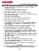
Warranty and Registration LA 9081 LDR 10-17-2016 Swing-N-Slide® MANUFACTURERS LIMITED WARRANTY Swing-N-Slide® demonstrates our commitment to providing quality residential playground products. MANUFACTURER’S LIFETIME LIMITED WARRANTY Swing-N-Slide® warrants its thermoformed slides and climbing mountains to be free from defects in workmanship and materials, under normal use and conditions, for the lifetime of the product.
PRODUCT WARRANTY & REGISTRATION Please register online to properly initiate your product warranty & registration Quick & simple from home or mobile Record your purchase in our system Initiate product warranty Improved customer support Register your product online at www.OnlineWarranty.
Call our Customer Support Representatives Printed in USA