PB 8272 IMPORTANT!! PLEASE READ BEFORE BEGINNING ASSEMBLY!! Please make sure all lumber, hardware and accessory parts are accounted for. If you are missing anything, please DO NOT RETURN to the store where purchased. Please call our Customer Service Department at the number below.
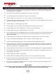
5CHGV[ %JGEMNKUV HQT 5YKPIÄ0Ä5NKFG 2NC[ 5GVU CPF #EEGUUQTKGU 1DUGTXKPI VJG HQNNQYKPI UVCVGUOGPVU CPF YCTPKPIU TGFWEGU VJG NKMGNKJQQF QH UGTKQWU QT HCVCN KPLWT[ 6JKU RNC[UGV JCU DGGP FGUKIPGF HQT WUG D[ C OCZKOWO QH GNGXGP QEEWRCPVU CV QPG VKOG JCXKPI C EQODKPGF YGKIJV QH RQWPFU 6JKU RNC[UGV KU KPVGPFGF HQT WUG D[ EJKNFTGP HTQO VQ [GCTU QH CIG 1PÄUKVG CFWNV UWRGTXKUKQP HQT EJKNFTGP QH CNN CIGU KU TGEQOOGPFGF +PUVTWEV EJKNFTGP PQV VQ YCNM ENQUG VQ KP HTQPV QH DG
2.
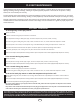
2.#;)4170& 574(#%+0) /#6'4+#.5 5'%6+10 1( 6*' %1057/'4 241&7%6 5#('6; %1//+55+105 176&114 *1/' 2.
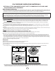
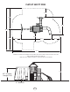
PLAYSET SAFETY ZONE 6’-0” 14’-0” 11’-9” 28’-0” 6’-0” 14’-0” 6’-0” 21’-1” 6’-0” 33’-1” MINIMUM USE ZONE FOR PLAY EQUIPMENT SHALL EXTEND NO LESS THAN 72” FROM ALL SIDES OF THE PLAY STRUCTURE. SWING USE ZONE EXTENDS NO LESS THAN 168”. SWINGS MUST HAVE A MINIMUM CLEARANCE OF 8” ABOVE THE PROTECTIVE SURFACING.
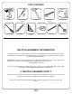
TOOLS REQUIRED DRILL SCREWDRIVER 1/2” & 7/16’’ SOCKETS & WRENCH PHILLIPS BIT HAMMER CARPENTER SQUARE SAFETY GLASSES ADJUSTABLE WRENCH 1/8” DRILL BIT TAPE MEASURE SHOVEL HELPFUL ASSEMBLY INFORMATION Your playset consists of several boxes or modules. It is important to ensure all lumber, accessories and hardware is accounted for. The following pages list the contents of each box. Use these pages to take an inventory of all parts.
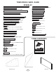
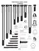
TOWER MODULE SA6051 / SA6022 BOARD LIST (4) [PF 6164] 3’’ x 3’’ x 94’’ (2) [PF 6063] 3/4’’ x 3-3/8’’ x 59-5/8’’ A-FRAME BASE (1) [PF 6020] 3’’ x 3’’ x 47-1/2’’ SWING BEAM SUPPORT (3) [PF 6006] 3/4’’ x 3-3/8’’ x 44-1/2’’ (1) [PF 6019] 2-11/16’’ x 5-3/8’’ x 89-1/2’’ SWING BEAM (2) [PF 6050] 3/4’’ x 3-3/8’’ x 43-1/2’’ (2) [PF 6004] 3/4’’ x 3-3/8’’ x 42’’ (1) [PF 6018] 2-11/16’’ x 3’’ x 62’’ A-FRAME SUPPORT (5) [PF 6005] 3/4’’ x 3-3/8’’ x 42’’ (2) [PF 6017] 1-3/8’’ x 3-3/8’’ x 83’’ A-FRAME LEGS (2) [PF 6
TOWER MODULE SA6051 / SA6022 COMPONENTS CONT.
TOWER MODULE SA6051 / SA6022 HARDWARE 1/4”-20 x 1-1/4” Hex Bolt (x12) 5/16”-18 x 6” Carriage Bolt (x3) 5/16”-18 x 2-1/2” Hex Bolt (x2) 5/16”-18 x 3-1/4” Hex Bolt (x2) 5/16”-18 x 3-1/2” Hex Bolt (x4) 5/16”-18 x 4” Hex Bolt (x5) 5/16”-18 x 6” Hex Bolt (x2) 5/16”-18 x 7” Hex Bolt (x1) 5/16”-18 x 8-1/2” Hex Bolt (x1) 5/16-18 T-Nut (x28) Small 1/4’’ Loc Washer (x12) 5/16” Washer (x24) 1/4’’ Washer (x16) Weld-Nut (x12) 5/16’’ Loc Washer (x12) #8 x 1/2” Pan Screw (x2) #12 x 3/4” Pan Screw (x14) 5/16-
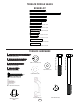
TERRACE MODULE SA6001 BOARD LIST (1) [PF 6061] 1-1/2’’ x 1-1/2’’ x 40’’ (2) [PF 6028] 1-3/8’’ x 3’’ x 79’’ (2) [PF 6026] 1’’ x 3-3/8’’ x 42’’ (3) [PF 6005] 3/4’’ x 3-3/8’’ x 42’’ (4) [PF 6025] 3/4’’ x 3-3/8’’ x 29-1/4’’ (3) [PF 6024] 3/4’’ x 3-3/8’’ x 27-3/4’’ (2) [PF 6150] 3/4’’ x 3-3/8’’ x 24-3/4’’ (1) [PF 6023] 3/4’’ x 3-3/8’’ x 22-1/2’’ (1) [PF 6022] 3/4’’ x 3-3/8’’ x 19-1/2’’ (10) [PF 6021] 5/8’’ x 5-3/8’’ x 30-3/4’’ (6) [PF 6135] 3/4’’ x 5-3/8’’ x 26-1/4’’ TERRACE HARDWARE 5/16’’ Loc Washer (x4) 1-3
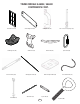
LADDER MODULE SA6005 BOARD LIST PICNIC TABLE MODULE SA6018 BOARD LIST (1) [PF 6034] 1-3/8’’ x 3-3/8’’ x 66-1/4’’ LADDER SUPPORT-L (1) [PF 6040] 1’’ x 5-3/8’’ x 41-1/2’’ BENCH (1) [PF 6035] 1-3/8’’ x 3-3/8’’ x 66-1/4’’ LADDER SUPPORT-R (2) [PF 6133] 3/4’’ x 3-3/8’’ x 41-1/2’’ TABLE (1) [PF 6029] 5/8’’ x 3-3/8’’ x 20-1/2‘’ (2) [PF 6038] 3/4’’ x 3-3/8’’ x 26-7/8’’ PICNIC TABLE LEG (5) [PF 6032] 1’’ x 3-3/8’’ x 18-1/2’’ (2) [PF 6037] 3/4’’ x 3-3/8’’ x 15-3/4’’ BENCH SUPPORT (2) [PF 6039] 3/4’’ x 3-3/8’’ x 9-3
MONKEY BAR SA6006 BOARD LIST (1) [PF 6041] 1-3/8’’ x 3-3/8’’ x 29-1/4’’ (2) [PF 6042] 1-3/8’’ x 3-3/8’’ x 32’’ (2) [PF 6043] 1-3/8’’ x 3-3/8’’ x 60’’ (2) [PF 6045] 1-3/8’’ x 3-3/8’’ x 79-7/8’’ (1) [PF 6044] 1’’ x 3-3/8’’ x 58’’ MONKEY BAR HARDWARE 5/16”-18 x 3-1/2” Hex Bolt (x2) 5/16”-18 x 3” Hex Bolt (x2) 2-1/2” Pan Head Screw (x18) 5/16”-18 x 2” Hex Bolt (x2) 5/16”-18 x 1-1/2” Hex Bolt (x6) 2-1/2” Deck Screw (x12) 5/16” Loc Nut (x4) 1-1/4” Pan Head Screw (x14) 5/16-18 T-Nut (x8) Small Anchor It (x
SIDEWINDER BOARD LIST WOOD ROOF BOARD LIST (2) [PF 6147] 1-3/8’’ x 3-3/8’’ x 36’’ (2) [PF 6148] 1-3/8’’ x 3-3/8’’ x 15-1/4’’ (18) [PF 6055] 1/2’’ x 5’’ x 47-1/2’’ SHINGLE (2) [PF 6061] 1-1/2’’ x 1-1/2’’ x 40’’ HARDWARE 1-5/8” Deck Screw (x96) Sidewinder Slide (x1) HARDWARE 2-1/2” Deck Screw (x10) 1-1/4” Deck Screw (x2) #14 x 1” Truss Screw (x6) 5/16” Washer (x18) 13 5/16”-18 x 3/4” Hex Bolt (x9) 5/16” Loc Nut (x9)
STEP 1 6’’ 47-1/2’’ Flush 6’’ (3) 2-1/2’’ Screws /8’’ 9-5 5 x /8’’ 3-3 SE x ’ A ’ 3/4 ME B 3 6 RA 60 A-F PF (3) 2-1/2’’ Screws 1’’ 010 6 PF ’’ -3/8 3 x /2’’ 7-1 4 x T-Nut Small PF 6164 3’’ x 3’’ x 94’’ PF 6164 3’’ x 3’’ x 94’’ (2) 2-1/2’’ Screws 5/16-18 X 4’’ Hex Head Bolt 5/16’’ Washer 5/16’’Loc-Washer 59-1/4’’ PF /8’’ 3-3 x ’’ 3/4 6 0 60 /2’’ 4-1 4 x FRAME A (2) 2-1/2’’ Screws 1-1/2’’ BOTH SIDES Hint!! Use parts from your Tower Box. 2-1/2” Deck Screw (x14) 1.
STEP 2 6’’ (3) 2-1/2’’ Screws Flush 6’’ PF 6164 3’’ x 3’’ x 94’’ (3) 2-1/2’’ Screws ’’ 5/8 59x /8’’ 3-3 SE x BA /4’’ 3 3 AME 6 0 R 6 A-F PF 0 601 F P /8’’ 3-3 x 1’’ PF 6164 3’’ x 3’’ x 94’’ 47-1/2’’ /2’’ 7-1 4 x T-Nut Small (2) 2-1/2’’ Screws 5/16-18 X 4’’ Hex Head Bolt PF ’’ 3/4 6 0 60 ’’ x -3/8 3 x 5/16’’ Washer ’’ 1/2 44- 5/16’’Loc-Washer (2) 2-1/2’’ Screws 59-1/4’’ (2) 2-1/2’’ Screws 31’’ 6 600 F P /8’’ 3-3 x ’’ 3/4 /2’’ 4-1 4 x (2) 2-1/2’’ Screws FRAME B 1-1/2’’ ALL JOINTS 2
STEP 3 PF 600 53 /4’’ x (3) 2-1/2’’ Screws Check to make sure structure is square PF 600 53 /4’’ x Flush 3-3 /8’’ x 42’ ’ (3) 2-1/2’’ Screws PF 600 43 /4’’ x 3-3 /8’’ x 42’ ’ 59-1/4’’ Flush (2) 2-1/2’’ Screws PF 600 53 /4’’ x 3-3 /8’’ x 42’ ’ (3) 2-1/2’’ Screws FRAME A 2-1/2” Deck Screw (x11) 1. Attach support boards to Frame A as shown.
STEP 4 (3) 2-1/2’’ Screws Check to make sure structure is square (3) 2-1/2’’ Screws (2) 2-1/2’’ Screws FRAME B (3) 2-1/2’’ Screws FRAME A 2-1/2” Deck Screw (x11) 1. Attach Frame A to Frame B as shown.
STEP 5 (2) PF 6149 1-3/8’’ x 3-3/8’’ x 15-1/2’’ DECK SUPPORT Flush NOTE: Insert Hardware From Outside Flush (3) 1-3/4’’ Screw per joint (4) 3’’ Screw 1-3/4” Deck Screw (x6) 3” Deck Screw (x4) 1. Install Deck Supports as shown.
STEP 6 PF 6003 3/4’’ x 3-3/8’’ x 35-7/8’’ (6) 1-3/4’’ Screws (6) 1-3/4’’ Screws PF 6003 3/4’’ x 3-3/8’’ x 35-7/8’’ (2) 2-1/2’’ Screws 16-1/2’’ PF 6011 1’’ x 3-3/8’’ x 47-1/2’’ 16-1/2’’ PF 6003 3/4’’ x 3-3/8’’ x 35-7/8’’ PF 6003 3/4’’ x 3-3/8’’ x 35-7/8’’ PF 6011 1’’ x 3-3/8’’ x 47-1/2’’ 1-3/4” Deck Screw (x12) TOP VIEW 2-1/2” Deck Screw (x2) 1. Install Deck Boards as shown.
STEP 7 (7) PF 6008 3/4’’ x 5-3/8’’ x 42’’ (6) 1-3/4’’ Screws per board 1-3/4” Deck Screw (x42) 1. Install Deck Boards as shown. NOTE: Standard gap between deck boards is 3/8’’.
STEP 8 PF 6002 3/4’’ x 3-3/8’’ x 22-1/2’’ (2) 2-1/2’’ Screws Flush Flush PF 6005 3/4’’ x 3-3/8’’ x 42’’ (2) 2-1/2’’ Screws (3) 2-1/2’’ Screws PF 6002 3/4’’ x 3-3/8’’ x 22-1/2’’ Flush (3) 2-1/2’’ Screws 31’’ PF 6005 3/4’’ x 3-3/8’’ x 42’’ (3) 2-1/2’’ Screws per joint 2-1/2” Deck Screw (x16) 1. Attach Boards as shown.
STEP 9 Check to make sure structure is square x 1’’ 026 6 PF x /8’’ 3-3 ’ 42’ 47-1/4’’ (2) 2-1/2’’ Screws FRAME A 5/16-18 X 4’’ Hex Head Bolt 5/16’’Loc-Washer 5/16’’ Washer Hint!! Use parts from your Terrace Box. T-Nut Small 2-1/2” Deck Screw (x4) 1. Install Deck Support Board as shown.
STEP 10 Check to make sure structure is square PF ’’ x 3/4 5 600 x /8’’ 3-3 ’ 42’ PF 6028 1-3/8’’ x 3’’ x 79’’ PF 6028 1-3/8’’ x 3’’ x 79’’ (3) 2’’ Screws Flush ’’ 3/4 5 0 60 PF Flush (3) 2’’ Screws ’’ x -3/8 3 x ’ 42’ (3) 2’’ Screws (3) 2’’ Screws FRAME C 2” Deck Screw (x12) 1. Assemble Frame C as shown.
STEP 11 Check to make sure structure is square ’’ 61 2 0 6 PF ’’ x -3/8 3 x ’ 42’ 5/16-18 X 2’’ Hex Head Bolt 47-1/4’’ 5/16’’Loc-Washer 5/16’’ Washer (2) 2’’ Screws T-Nut Small 2” Deck Screw (x4) 1. Install Deck Support Board as shown.
STEP 12 (2) 2-1/2’’ Screws Check to make sure structure is square 1 604 PF /8’’ 3-3 x /8’’ 1-3 Flush ’’ 1/4 9 x2 Flush ’’ 025 29-1/4 6 PF 8’’ x -3/ x3 ’ ’ 4 3/ (2) 2-1/2’’ Screws Flush (2) 2-1/2’’ Screws PF ’’ 3/4 5 2 60 ’’ -3/8 3 x (2) 2-1/2’’ Screws /4’’ 9-1 2 x ’’ 024 27-3/4 6 PF 8’’ x -3/ x3 ’ ’ 4 3/ 50-5/8’’ Flush FRAME C PF Hint!! Use parts from your Monkey Bars Box. 2-1/2” Deck Screw (x10) 1. Install Frame Support Boards as shown.
STEP 13 Check to make sure structure is square (3) 2-1/2’’ Screws (3) 2-1/2’’ Screws (3) 2-1/2’’ Screws (2) 2-1/2’’ Screws (2) 2-1/2’’ Screws FRAME C 2-1/2” Deck Screw (x13) 1. Attach Frame C to Tower as shown.
STEP 14 (2) 1-3/4’’ Screws PF 6150 3/4’’ x 3-3/8’’ x 24-3/4’’ PF 6150 3/4’’ x 3-3/8’’ x 24-3/4’’ (2) 1-3/4’’ Screws (2) 1-3/4’’ Screws (1) 1-3/4’’ Screws (2) 1-3/4’’ Screws PF 6061 1-1/2’’ x 1-1/2’’ x 40’’ PF 6061 1-1/2’’ x 1-1/2’’ x 40’’ PF 6150 3/4’’ x 3-3/8’’ x 24-3/4’’ (1) 1-3/4’’ Screws 10-5/8’’ 10-5/8’’ PF 6150 3/4’’ x 3-3/8’’ x 24-3/4’’ TOP VIEW 1-3/4” Deck Screw (x10) 1. Install Deck Boards as shown.
STEP 15 (6) PF 6135 3/4’’ x 5-3/8’’ x 26-1/4’’ (6) 1-3/4’’ Screws per board 1-3/4” Deck Screw (x36) 1. Install Deck Boards as shown. NOTE: Standard gap between deck boards is 7/16’’.
STEP 16 PF 6022 3/4’’ x 3-3/8’’ x 19-1/2’’ (3) 2’’ Screws 50-5/8’’ 2” Deck Screw (x6) 1. Install Barrier Support Boards as shown.
STEP 17 PF 6004 3/4’’ x 3-3/8’’ x 42’’ (6) 2-1/2’’ Screws PF 6005 3/4’’ x 3-3/8’’ x 42’’ 5-3/8’’ 53-7/8’’ 2-1/2” Deck Screw (x12) 1. Attach Gap Filler Boards as shown.
STEP 18 (3) PF 6021 5/8’’ x 5-3/8’’ x 30-3/4’’ (4) 1-1/4’’ Screws per board 1/8’’ GAP BETWEEN BOARDS Panel Bracket #12 x 3/4” Pan Screw (x4) (4) 3/4’’ Pan Screws INSIDE VIEW 1-1/4” Deck Screw (x16) 1. Install Barrier Boards as shown.
STEP 19 (3) PF 6021 5/8’’ x 5-3/8’’ x 30-3/4’’ 2-1/8’’ (4) 1-1/4’’ Screws per board 1-1/4” Deck Screw (x12) 1. Attach Barrier Boards as shown.
STEP 20 1’’ 3-1/8’’ 3-1/8’’ 1’’ 1-5/8’’ PF 6172 5/8’’ x 3-3/8’’ x 11-1/2’’ PRE-DRILL (4) 1/8’’ HOLES PF 6001 5/8’’ x 5-3/8’’ x 9-1/4’’ PF 6172 5/8’’ x 3-3/8’’ x 11-1/2’’ PF 6000 5/8’’ x 5-3/8’’ x 33-3/4’’ PF 6000 5/8’’ x 5-3/8’’ x 33-3/4’’ (4) 30mm Screws per board FROM BACK SIDE 17-3/8’’ PF 6172 5/8’’ x 3-3/8’’ x 11-1/2’’ 4-7/8’’ (10) 3/4’’ Screws per Window Frame PF 6001 5/8’’ x 5-3/8’’ x 9-1/4’’ 3’’ 3’’ x2 x2 Hint!! Use parts from your Tower Box.
STEP 21 1’’ (2) 1-1/4’’ Screws per board (2) 1-1/4’’ Screws per board (2) 1-1/4’’ Screws per board (2) 1-1/4’’ Screws per board Panel Bracket (4) 3/4’’ Pan Screws 1-1/4” Deck Screw (x24) #12 x 3/4” Pan Screw (x8) 1. Install Window Panels.
STEP 22 PF 6020 3’’ x 3’’ x 47-1/2’’ SWING BEAM SUPPORT TOP OF BEAM SUPPORT 84’’ FROM BOTTOM OF POST Loc Nut 5/16’’ Washer Wood Loc-Washer 5/16-18 X 6’’ Carriage Bolt 1. Install Swing beam support as shown.
STEP 23 PF 6019 2-11/16’’x5-3/8’’x93’’ Swing Beam 5/16’’ T-Nut Large 5-1/2’’ Swing Hanger Beam Clamp 2 1 3 x4 Correct Orientation 4 (4) 1-1/4’’ Deck Screws 5 1-1/4” Deck Screw (x24) 1. Attach Swing Hanger(s) to swing beam as shown. NOTE: Make certain hanger and plate are snug against the bottom of the swing beam, (Fig 5), before installing screws.
STEP 24 PF 6018 2-11/16’’x3’’x62’’ A-Frame SB Support 5/16”-18 x 7” Hex Head Bolt (1) 3’’ Screws (1) 3’’ Screws 5/16” Washer 5/16” Washer 5/16” Loc Nut (2) PF 6017 1-3/8’’x3-3/8’’x83’’ A-Frame 5/16”-18 x 2-1/2” Hex Head Bolt 5/16” Loc Washer 5/16” Washer 5/16-18 T-Nut Small 5/16” Washer 5/16” Loc Washer (2) 2-1/2’’ Screws 5/16”-18 x 4” Hex Head Bolt (2) 2-1/2’’ Screws (2) 2-1/2’’ Screws 5/16-18 T-Nut Small PF 6016 1-3/8’’x3-3/8’’x58’’ A-Frame Support 5/16” Loc Washer 5/16” Washer 5/16-18 T-Nut S
STEP 25 (2) Swing Beam Bracket 5/16”-18 x 3-1/2” Hex Head Bolt x2 5/16” Washer 5/16” Loc Nut 5/16”-18 x 3-1/2” Hex Head Bolt 5/16” Washer x2 5/16” Washer 5/16” Washer 5/16” Loc Nut 1. Attach Swing Beam Bracket to A-Frame & Swing Beam as shown.
STEP 26 Beam Brace 5/16”-18 x 3 1/4” Hex Head Bolt 5/16” Loc Washer 5/16” Washer 5/16-18 T-Nut Small 1. Install Swing Beam Brace as shown.
STEP 27 5/16”-18 x 6” Carriage Bolt 5/16”-18 x 8-1/2” Hex Head Bolt 5/16” Loc Washer 5/16” Washer 5/16” Wood Loc Washer 5/16” Washer 5/16-18 T-Nut Small 5/16” Loc Nut 1. Install Swing Beam as shown.
STEP 28 (6) PF 6000 5/8’’ x 5-3/8’’ x 33-3/4’’ (4) 1-1/4’’ Screws per board 1-1/4” Deck Screw (x24) 1. Install Barrier Boards as shown. NOTE: Standard gap between deck boards is 1/2’’.
STEP 29 (1) 3’’ Deck Screws 1-5/8’’ 1-5/8’’ 13-1/2’’ PF Check to make sure structure is square 60 62 PF ’’ 21 6 60 ’’ 3/8 x3 ’’ 1/2 2 x4 E AM R F AF O RO PF 6058 5/8’’ x 3-3/8’’ x 30’’ (4) 1-1/4’’ Deck Screws 1’’ x3 -3 /8’ ’x 42 -1 /2’ ’R OO FA -F RA ME x2 3/4’’ CENTERED PF 6060 5/8’’ x 5-3/8’’ x 13’’ SUN (4) 1-1/4’’ 30mm Screws 30mm Deck Screw (x4) x2 3” Deck Screw (x2) 1-1/4” Deck Screw (x8) 1. Assemble Roof A-Frames as shown.
STEP 30 (4) 30mm Screws (6) 1-1/4’’ Screws (1) PF 6056 5/8’’ x 2’’ x 10’’ (2) PF 6059 5/8’’ x 2’’ x 7’’ x2 CENTERED (2) 2-1/2’’ Screws 2’’ -1/ 3 4 PF 6053 1-3/8’’ x 3-3/8’’ x 43-1/2’’ (2) 2-1/2’’ Screws 2’’ -1/ 3 4 1-1/4” Deck Screw (x12) 30mm Deck Screw (x8) 2-1/2” Deck Screw (x4) 1. Assemble the Roof frame as shown.
(5) PF 6055 1/2’’ x 5’’ x 47-1/2’’ SHINGLE Per Side STEP 31 1’’ OVERHANG BOTH SIDES (4) 1-5/8’’ Deck Screws per board ’’ 21 /2’’ 1 45 (1) 1-5/8’’ Deck Screw per board ’’ 21 /2’’ 1 45 (2) PF 6061 1-1/2’’ x 1-1/2’’ x 40’’ (4) PF 6055 1/2’’ x 5’’ x 47-1/2’’ SHINGLE Per Side (2) PF 6061 1-1/2’’ x 1-1/2’’ x 40’’ 21 ’’ 21 ’’ UNDERSIDE VIEW (5) 1-5/8’’ Deck Screws per board 1-5/8” Deck Screw (x90) Hint!! Use parts from your Wood Roof Box. 1. Assemble Roof as shown.
STEP 32 Flush At Ends (3) 1-5/8’’ Screws (3) 1-5/8’’ Screws (3) 1-5/8’’ Screws (3) 1-5/8’’ Screws NOTE: Secure Roof from the INSIDE 1-5/8” Deck Screw (x12) 1. Attach Roof Frame to Tower as shown. NOTE: Secure roof from inside the tower.
STEP 33 x /4’’ 03 5 0 6 PF /2’’ 3-1 4 x /8’’ 3-3 (4) 2’’ Screws PF 2” Deck Screw (x8) 1. Attach Roof Side Support Boards as shown.
STEP 34 x -3/8’’ 035 1 PF 6 ’’ 3-3/8 x 66- -1/4’’ RT-R 6 ’’ x 6 PPO 3-3/8 R SU E LADD 1/4’’ x -3/8’’ 034 1 PF 6 -L ORT UPP ER S LADD (2) 2-1/2’’ Screws per Rung (2) 2-1/2’’ Screws per Rung (5) PF 6032 1’’ x 3-3/8’’ x 18-1/2’’ PF 6029 5/8’’ x 3-3/8’’ x 20-1/2‘’ (4) 2-1/2’’ Screws 2’’ Hint!! Use parts from your Ladder Box. 2-1/2” Deck Screw (x24) 1. Assembly Ladder as shown.
STEP 35 (3) 2-1/2’’ Screws Panel Bracket (4) 3/4’’ Pan Screw Underdeck View 2-1/2” Deck Screw (x3) #12 x 3/4” Pan Screw (x4) 1. Attach Ladder to Tower as shown.
STEP 36 ALIGN SCREWS WITH PRE DRILLS (1) PF 6013 5/8’’ x 5-3/8’’ x 22-3/4’’ ROCKWALL BOARD (1) PF 6013 5/8’’ x 5-3/8’’ x 22-3/4’’ ROCKWALL BOARD 2” Deck Screw (x32) 1. Align and install rock wall boards to the image above.
STEP 37 Panel Bracket (4) 3/4’’ Pan Screw (3) 2-1/2’’ Screws Under Deck View 2-1/2” Deck Screw (x3) #12 x 3/4” Pan Screw (x4) 1. Attach Rock Wall as shown.
STEP 38 (2) Weld Nuts (2) 1-1/4’’ Hex Head Bolts (2) 1/4’’Flat Washer Per Rock (2) 1/4’’ Loc-Washer Per Rock 1. Attach Climbing Rocks as shown.
STEP 39 31’’ Flush PF 6024 3/4’’ x 3-3/8’’ x 27-3/4’’ (2) 2-1/2’’ Screws per side Flush 1-1/4” Deck Screw (x18) (4) PF 6021 5/8’’ x 5-3/8’’ x 30-3/4’’ 5/8’’ GAP BETWEEN ALL BOARDS 2-1/2” Deck Screw (x4) 1. Install Barrier Support and Barrier Boards as shown.
STEP 40 (2) PF 6039 3/4’’ x 3-3/8’’ x 9-3/4’’ TABLE SUPPORT (2) PF 6037 3/4’’ x 3-3/8’’ x 15-3/4’’ BENCH SUPPORT (4) 1-1/4’’ Screws (4) 1-1/4’’ Screws 3’’ 3’’ 11-3/8’’ Flush 25’’ 6-7/8’’ 6-7/8’’ (2) PF 6038 3/4’’ x 3-3/8’’ x 26-7/8’’ PICNIC TABLE LEG 13-3/4’’ Flush Check to make sure structure is square (4) 2’’ Screws 1-1/2’’ BOTH SIDES (2) PF 6133 3/4’’ x 3-3/8’’ x 41-1/2’’ TABLE PF 6040 1’’ x 5-3/8’’ x 41-1/2’’ BENCH (2) 2’’ Screws (4) 2’’ Screws (2) 2’’ Screws 1-1/2’’ BOTH SIDES Hint!! U
(2) [PF 6014] 1-1/2’’ x 3-1/2’’ x 36’’ STEP 41 Hex Head Bolt 5/16’’ Washer 5/16’’ Washer 5/16’’Loc-Nut (4) 2-1/2’’ Screws per board 30-1/2’’ (4) 2-1/2’’ Screws per board 12’’ (2) [PF 6012] 1-1/2’’ x 3-1/2’’ x 15’’ (4) 1’’ Truss Screws (1) 1’’ Truss Head Screw per side Attach brace here (2) 1-1/4’’ Deck Screws 12’’ 2” PF 6009 1-3/8’’x3-3/8’’x17-1/4’’ Slide Stake 59’’ Grade 2-1/2” Deck Screw (x8) 1-1/4” Deck Screw (x2) 1” Truss Screw (x6) 1.
STEP 42 Flush (2) ‘L’ Brackets (3) 1-1/4’’ Pan Head Screws per L Bracket (2) PF 6043 1-3/8’’ x 3-3/8’’ x 60’’ 49-1/4’’ (5) Short Monkey Bar Rungs 38-1/4’’ (2) 2-1/2’’ Pan Head Screws per rung 27-1/4’’ 16-1/4’’ 5-1/4’’ 19’’ T-Nut Small 5/16’’ Washer 5/16’’Loc-Washer 5/16-18 X 1-1/2’’ Hex Head Bolt (2) Triangle Brackets 2-1/2” Pan Head Screw (x10) Hint!! Use parts from your Monkey Bar Box. PLACE NO BOLTS HERE 1. Assemble Horizontal Ladder as shown.
(2) PF 6045 1-3/8’’ x 3-3/8’’ x 79-7/8’’ STEP 43 (3) Monkey Bar Rungs 36-1/4’’ (2) 2-1/2’’ Pan Head Screws per rung 24-1/2’’ 12-3/4’’ Flush 22’’ PF 6044 1’’ x 3-3/8’’ x 58’’ 5/16’’ Washer 5/16’’Loc-Washer T-Nut Small (4) 2-1/2’’ Screws (2) PF 6042 1-3/8’’ x 3-3/8’’ x 32’’ 5/16-18 X 3-1/2’’ Hex Head Bolt 5/16’’ Washer 5/16’’Loc-Washer 5/16-18 X 2’’ Hex Head Bolt T-Nut Small 2-1/2” Pan Head Screw (x6) 2-1/2” Deck Screw (x4) 1. Assemble vertical ladder as shown.
STEP 44 5/16-18 X 3’’ Hex Head Bolt 5/16’’Loc-Washer 5/16’’ Washer T-Nut Small 5/16-18 X 1-1/2’’ Hex Head Bolt 5/16’’Loc-Washer 5/16’’ Washer T-Nut Small Flush (3) 1-1/4’’ Pan Head Screws per L Bracket 1. Assemble and attach Monkey Bar Assembly as shown.
STEP 45 1/4” Washer 1/4’’ x 1-3/4” Pan Screw 11” 1/2” Pan Screw (x2) 1-3/4” Pan Screw (x2) 1. Attach Safety Handle and I.D. Tag as shown.
STEP 46 Eye Bolt Eye bolts should be oriented perpendicular with Glider seat. o 90 TOP VIEW Eye Bolt It is helpful to use a screwdriver to hold eye bolt in place when tightening lock nut. Tighten Lock Nut until three (3) threads are exposed. Flat Washer Hex Bolt Flat Washer Flat Washer Lock Nut Tighten Lock Nut until three (3) threads are exposed. 1. Assemble Two child Swing as shown.
STEP 47 Quick Link x4 Glider Chain Chain End Link Tighten clips securely with a wrench. µ PLQLPXP EHWZHHQ *OLGHU DQG JURXQG $GMXVW &KDLQV DW 7RS FINAL INSPECTION ,03257$17 ,QVSHFW DQG FRQÀUP tightness of all Lock-Nuts and Quick Links. !IMPORTANT! Attach (2) Chains per Swing Hanger using quick links µ PLQLPXP EHWZHHQ *OLGHU DQG JURXQG $GMXVW &KDLQV DW 7RS 1. Finish Two child Swing assembly as shown.
BOTTOM OF SEAT LOGO ON TOP BOTTOM OF SEAT PLASTIC COATED END LOGO ON TOP STEP 48 6ZLQJ 6HDW $VVHPEO\ 1. Take one length of chain and place the outermost link of coated chain through the Quick Link as shown. 2. Place the Quick Link through the Grommet of the swing seat as shown. 3. Tighten the threaded sleeve of the Quick Link with a suitably sized wrench so that the seat is securely attached and the Quick Link cannot be easily loosened. Repeat for second chain, Quick Link and Swing Seat Grommet. 4.
STEP 49 5/16” Washer Fold up Anchor-It Strap 1-1/2” Lag Screw Anchor-It 5/16’’ x 1-1/2” Lag Screw (x4) 3ODFH VZLQJ VHW LQ ¿QDO ORFDWLRQ DQG PRXQW $QFKRU ,W V DW ORFDWLRQV FLUFOHG DERYH 2. Twist the Anchor-It into the ground until only the loop is exposed. 3. Place Anchor-It Strap thru loop, fold the ends together and attach to the unit as shown. Note: Keep as little play as possible using any of the holes in the strap that work best.
Swing-N-Slide® MANUFACTURERS LIMITED WARRANTY WARRANTY REGISTRATION: Please complete your warranty registration to properly validate your product warranty. Register your product online at: www.OnlineWarranty.net Swing-N-Slide® takes great pride in the quality and durability of our products. Our Manufacturer’s Limited Warranty SURYLGHV FRQ¿GHQFH DQG GHPRQVWUDWHV RXU FRPPLWPHQW WR providing quality residential playground products.
PRODUCT WARRANTY & REGISTRATION Please register online to properly initiate your product warranty & registration %HQH¿WV RI UHJLVWHULQJ RQOLQH Ŷ Quick & simple from home or mobile Ŷ Record your purchase in our system Ŷ Initiate product warranty Ŷ Improved customer support Ŷ 1RWL¿FDWLRQ RI QHZ SURGXFW LQIRUPDWLRQ Register your product online at www.OnlineWarranty.
Got Questions? We’ve got answers! Call our Customer Support Representatives 1-800-888-1232 Available Monday - Friday, 7am - 5pm (CST) Weekend support available April through July Technical support from experienced Swing-N-Slide customer service representatives who have actually built a swing set themselves. © Swing-N-Slide Inc.