
Installation Guide

13
Assembly Instructions
slide bracket
exit section
"!! $
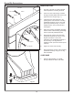
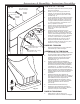
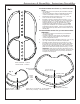
Position the slide bracket between the slide and
activity center (Fig. 13). Remove appropriate
bolts from the slide (the fourth and fifth bolts as
i
ndicated), Attach bracket to the underside of
the seam using the previously removed
hardware (Fig. 13).
If necessary, move slide towards the activity
center until the slide bracket makes contact with
the unit. Using holes in the bracket (indicated by
arrows in Fig. 13) as a guide, mark and drill 1/8"
pilot holes (1" deep). !: You may need to
temporarily remove the slide bracket to drill the
pilot holes.
Re-attach bracket (if necessary) and secure it to
the unit using two 1-1/2" lag bolts .
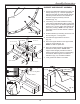
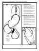
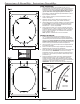
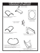
Assemble the support base as shown in
(Fig. 14).
Attach the support bracket to the support base
using two 2" lag bolts (Fig. 15).
!Pre-drill 1/8" pilot holes.
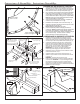
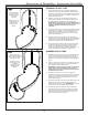
Place the support beneath the slide base and
determine its final position. !Slide
support should fit tightly beneath the slide to
assure proper support. Remove corresponding
nut and bolt, attach support to the slide as
indicated in (Fig. 16). Re-attach hardware.
Level grade at the bottom of the slide.
-+
1-1/2" bolt
2" x 4" x 9-1/4"
2" x 4" x 7"
2" x 4" x 20"
2" x 4" x 20"
washer
loc nuts
2" x 4" x 9-1/4"
-+
-+
2-1/2" Screws
Support Bracket
%A4A8;;
FLUSH
-+
2-1/2" Screws
2-1/2" Screws
(2) 1-1/2" Lag Bolts