
Instructions / Assembly


17
Assembly Instructions
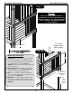
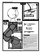
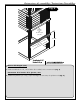
FIGURE 14
2" x 4" x 8-1/4"
2" x 4" x 11-1/4''
2" x 4" x 18"
2" x 4" x 18"
2-1/2" Screws
2-1/2" Screws
2" x 4" x 8-1/4"
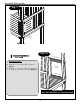
(2) 2" Lag Screws
Support Bracket
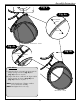
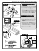
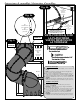
Fig. 10
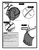
Fig. 10a
Fig. 10b
SUPPORT AND BRACKET
ASSEMBLY
1. Assemble the support base as shown in (Fig. 10).
2. Attach the support bracket to the support base using
two lag bolts (Fig. 10a).
NOTE: Pre-drill 1/8" pilot holes.
3. Place the support beneath the Exit and determine its
final position. NOTE: Slide support should fit tightly
beneath the slide to assure proper support. Remove
corresponding nut and bolt, attach support to the slide
as indicated in (Fig. 1
0b). Re-attach hardware.
4. Level
grade at the bottom of the slide.
Pre-Drill
2'' Lag screw
2-1/2'' screw
Loc Nut
Washer
Hex Head
Bolt
FLUSH