
Installation Guide

Secure the filter tank foot (continued)
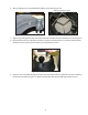
1. With the filter tank inlet aligned toward the pump, identify which screw holes in the system base align
with the screw holes in the filter tank foot (Figure 7).
2. Refer to Figure 6 on the previous page, and to the table below to determine the correct washer/screw/
threaded brass insert set for the hole pattern. Note: Each filter model will use either the 1/4-20 or the
10-24 hardware—never both.
3. Remove the filter tank base from the system base.
For the 1/4-20 x 1-1/2” screw, the 1/4-20 brass insert, and the 1/4 x 5/8 washer
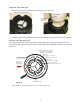
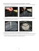
4. Hand seat the 1/4-20 brass insert into the appropriate screw hole in the system base (Figure 8)
5. Using a flat-head screw driver, drive the 1/4-20 brass insert into the hole in the system base. The blade
of the screw driver must be wide enough to catch both slots in the end of the insert (Figure 9).
Figure 9
Filter model
Screw
Brass Insert Washer
PLM, PLD 1/4-20 x 1-1/2" Long 1/4-20 1/4 x 5/8
PXC #10-24 x 2" Long 10-24 10 x 7/16
PRC, PRD #10-24 x 2" Long 10-24 10 x 7/16
Clean & Clear, Warrior 1/4-20 x 1-1/2" Long 1/4-20 1/4 x 5/8
4
Figure 8
Hand seat brass
insert
Screw hole–system base (a second
such screw hole is located 180°
opposite this one)
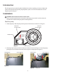
Figure 7
Align screw hole in
filter tank foot with
screw hole in system
base
Screw hole–filter tank foot (a second
such screw hole is located 180°
opposite this one)