
Installation Guide

3
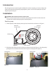
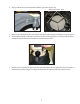
Figure 4
Filter end of system base
Figure 5
Filter tank
inlet
Position the filter tank
so that the filter tank
inlet faces the pump
* Filter tanks for sand systems neither use nor require screw holes.
Seat the filter tank foot
1. Place the filter tank foot on the filter end of the system base (Figure 4).
2. Position the filter tank foot so that the filter tank inlet faces the pump end of the system base (Figure 5).
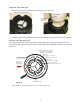
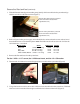
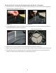
Secure the filter tank foot
The system base provides screw holes to align with the screw holes* in the foot of the filter tank. The
system base supports the following filter models: PLM, PLD, PXC, PRC, PRD, Clean & Clear
®
, Warrior
®
(Figure 6).
Figure 6
PXC
Takes #10-24 x 2” long screw
Clean & Clear, Warrior
Takes 1/4-20 x 1-1/2” long screw
PRC, PRD
Takes #10-24 x 2” long screw
PLM, PLD
Takes 1/4-20 x 1-1/2” long screw
To pump
The filter tank
inlet should point
toward the pump
The screw holes in the filter tank base
will line up with one of the following
hole patterns in the system base:
Filter end of system base