H20-220 ULTIMA “XT” These instructions are updated on a regular basis. Please visit our web site at www.swiftech.com Copyright Swiftech 2010 – All rights reserved – Last revision date: 4-27-10- Information subject to change without notice – URL: http://www.swiftech.com Rouchon Industries, Inc., dba Swiftech – 151 West Victoria Street, Long Beach, CA 90803 – Tel. 310-763-0336 – Fax 310-763-7095 - E Mail: help@swiftech.
Packing List QTY 1 1 1 1 6 1 1 ITEM APOGEE™ XT water-block, including socket 1366, socket 1156 and socket 775 hold-down plates for all Intel Core® desktop microprocessors. Important note: Free Upgrade available (see terms and conditions) for AMD® socket 754, 939, and AM2, as well as Intel® socket 771 (Xeon series) Server form factor MCP655-B pump, including mounting hardware and (2) ½” hose clamps MCRES-Micro Rev.
TABLE OF CONTENTS I. PLANNING ............................................................................................................................................. 4 1. General Guidelines ................................................................................................................................. 4 2. Tube Routing .......................................................................................................................................... 4 II.
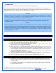
INTRODUCTION Congratulations on your purchase of a Swiftech™ H20-APEX liquid cooling system! This kit has been designed to facilitate the installation of the components with a minimum of case modifications. While all attempts have been made to make the installation of this system user friendly, please note that this system is intended for users that are well versed in installing computer components.
From a performance standpoint there is very little performance to be gained from strictly controlling the component sequence: the maximum difference in temperature between any two points of the liquid cooling circuit does not exceed 1ºC. Whenever possible, performance oriented users will typically want to route the radiator discharge(s) tube(s) to the inlet of the CPU cooler, since the fluid exiting the radiators is always the coolest.
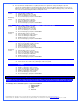
1. MCR220 RADIATOR INSTALLATION Preamble: The MCR220 dual 120mm radiator ships with the fans and the Radbox chassis already pre-assembled to the radiator. It is assumed in effect that users will take advantage of our Radbox concept (external radiator installation) due to the benefits it provides and ease of installation. In such context, the following installation guide describes this type of installation.
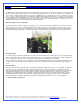
Installation Place the radiator assembly to the back panel of the computer in order to roughly estimate where it will fit best. You need to consider the following clearance issues: Exit cables and connectors from various PCI devices: the Radbox base plate can be moved in both vertical and horizontal directions to allow clearance for the cables.
Once satisfied with the position, bolt down the Radbox back-plate with the provided nylon nuts. Routing of the tubes thru the chassis: Many of the current chassis offered on the market now come with pre-drilled holes to route the tubing thru the chassis. If your chassis does not have this feature, it will be necessary to drill the holes yourself. Since the OD of the tubing that comes with your kit is ¾” , we recommend using a 1” bi-metal hole saw (shown below) to open up these holes.
2. APOGEE™ XT WATERBLOCK INSTALLATION Please refer to the separate installation guide included inside of the waterblock box. Re-installing the motherboard Once the APOGEE™ waterblock securely fastened to the motherboard, go-ahead and install the motherboard into the chassis, following the instructions provided in your motherboard installation guide. 3. PUMP INSTALLATION General Use The MCP655-B pump is a magnetically driven centrifugal pump featuring a 12 V DC motor.
In general, we recommend installation of the pump at the bottom of the chassis. The base of the pump features a soft neoprene pad coated with strong adhesive material. Once the final location for the pump has been determined, simply peel-off the pad’s protective paper, and press the pump against the chassis surface. The surface should be clean, and non greasy. Thru-bolts are also provided for permanent installation, and require drilling holes in the chassis.
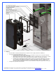
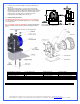
Figure 1 Port Usage definition Upper side port: “Inlet” as shown in figure 1 is the return line from the system Lower side port: “Outlet (to pump)” shown in figure 1 should always be connected to the pump inlet (directly if possible to facilitate filling of the system) The fill-port located on top of the unit is used to fill it up with coolant, and sealed with a chrome plated brass plug.
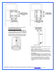
MCRes Micro Bracketry installation and examples 6 7 5 ITEM NO. 1 2 3 4 5 PART NUMBER BCKT1 BCKT2 90272A146-6-32x3-8-philips 6 7 91772A158-6-32X1.75 90760A007 DESCRIPTION "L" bracket "U" bracket 6-32 x 3/8” Philips screw 6-32 x 1 3/4" Philips screw 6-32 Nut w/teeth washer QTY . 1 2 3 2 3 FW150X437X092 Rubber Washer 437X150X092 2 93286A041-WASHER zinc plated washer 5 Note 1: rubber washer 6 should be inserted between either side of the reservoir ear and the U bracket 2.
5. 6. INSTALLING THE TUBING With one end of a tube connected to a startup component such as the water-block for example, roughly estimate the length that you will need to the next component, and cut the tube squarely with a pair of scissors. Work your way through the entire circuit in the same fashion, until you are satisfied with the tube routing. Always avoid sharp bends to prevent the tube from kinking.
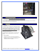
Example of installation 7. TROUBLESHOOTING Air keeps circulating into the circuit, long after the pump has primed: o There is a significant pocket of air trapped into the circuit. In most cases this will be due to the fact that the radiator and or the water-block where installed upside down. Temporarily dismount the device and re-orient right side-up until all the air has escaped back into the circuit. o The fluid level is too low: top-off the reservoir to the appropriate level.
9. Then, you will need to disconnect a line from one of the lowermost components. Typically, this would be the pump. You need to procure a bucket large enough to receive approximately 1 liter of fluid, and place the bucket underneath the connection that you intend to “break”. Disconnect the line, and place both ends into the bucket, until all the liquid is drained from the system. PERIODIC MAINTENANCE Every 6 months: dust off the radiator fins and fan.