
User guide


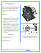

5. MCRES-MICRO RESERVOIR INSTALLATION
ITEM
NO.
PART NUMBER DESCRIPTION QTY.
1 MCRES-MICRO Reservoir 1
2
1-4“ NPSM x 3-8“ and 1-2“barb
Barb fitting
2 pairs
each
3 O-RING-9557K473 Barb fitting O-Ring 2
4 pg7-o-ring
Fill-cap o-ring
1
5 pg7-plug Pg7 Fill-cap 1
6 MOUNTING HARDWARE 3
90272A152-6-32x0500philips 6-32 x 7/8" (22mm) Philips screw 1
90760A007
6-32 Nut 1
washer-91007A614
Lock Washer
1
WASHER-RUBBER-437X150X092 Rubber Washer 1
7 panel 1
6a
6b
6c
6d
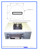
Figure 1
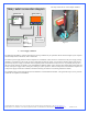
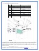
A. Installation
The MCRES-MICRO can be installed in any suitable location meeting its form factor requirements. For filling and bleeding purposes,
it is preferable to hold or to install the MCRES-MICRO at the highest point of the liquid cooling loop. However, once filled and
hermetically closed, the reservoir can be installed practically anywhere as long as it is kept upright as shown in figure 1. Also, to
facilitate the filling and bleeding operations, you might want to wait until the circuit has been filled-up before you fasten the reservoir
permanently to the chassis.
Copyright Swiftech 2005 – All rights reserved – Last revision date: 12-27-05 - Information subject to change without notice – URL: http://www.swiftnets.com
Rouchon Industries, Inc., dba Swiftech – 1703 E. 28
th
Street, Signal Hill, CA 90755 – Tel. 562-595-8009 – Fax 562-595-8769 - E Mail: Swiftech@swiftnets.com PAGE 29 of 32
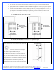
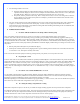
B. Fastening the device to the case