
User guide
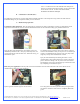
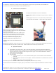
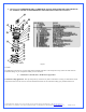
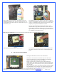
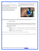
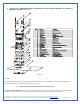
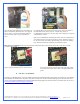
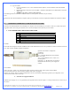
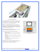

Figure 1
B. Relay Switch Installation
Copyright Swiftech 2005 – All rights reserved – Last revision date: 12-27-05 - Information subject to change without notice – URL: http://www.swiftnets.com
Rouchon Industries, Inc., dba Swiftech – 1703 E. 28
th
Street, Signal Hill, CA 90755 – Tel. 562-595-8009 – Fax 562-595-8769 - E Mail: Swiftech@swiftnets.com PAGE 20 of 32
Find a suitable placement to drill a hole for the A/C socket adapter.
Leave sufficient room under or above the hole to install the relay
switch circuit board. A ¼” minimum clearance will be required
between the circuit board and the edge of the hole.
Make a 1.25” (32mm) diameter hole in the case, using a 1 ¼” Bi-
Metal hole saw. De-burr the edges of the hole with sand paper.
Position and center the mounting plate over the hole as a template to
mark the locations of the plate’s mounting screws. Drill 2 holes of
.125” diameter for the mounting screws.
Install the mounting plate using the screws provided with your kit.
Insert the A/C socket inside the mounting plate.
Proceed with electrical connections as described in fig.3:
Black L wire from A/C socket to N\O (normally opened)
position on switch
Black L wire from S320-12 power supply to N\O position
on switch
White N wire from S320-12 power supply to N position on
A/C socket
Green Ground wire from S320-12 power supply to Ground
on A/C socket
The 4 pins Molex connector will then connect to the
computer power supply.
Note that connection of the TEC wires to the S320-12 power supply
will take place at the very end of the installation, once your
hydraulic circuit has been leak proofed (chapter 2.7)
Pump’s relay switch circuit board
A/C Soc ket
1.25"
Ho le
Sp a c i n g
N\O
+
_
0.25"
N\O
Figure 2