These instructions are updated on a regular basis. Please visit our web site at http://www.swiftnets.com Copyright Swiftech 2005 – All rights reserved – Last revision date: 12-27-05 - Information subject to change without notice – URL: http://www.swiftnets.com Rouchon Industries, Inc., dba Swiftech – 1703 E. 28th Street, Signal Hill, CA 90755 – Tel. 562-595-8009 – Fax 562-595-8769 - E Mail: Swiftech@swiftnets.
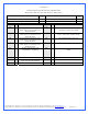
Packing List Included components check-marked per applicable model: H20-220-PT □ H20-220-775T □ H20-220-64T □ H20-220-AT □ Description Intel® Pentium® 4 (socket 478) Intel® Pentium® 4 (LGA775) Product Code PT 775T Product Code PT Qty Item 1 775T 1 64T 1 AT 1 ALL 1 MCW5002-PT thermoelectric waterblock, with (2) # 6 worm drive hose clamps & gaskets MCW5002-775T thermoelectric waterblock with (2) # 6 worm drive hose clamps & gaskets MCW5002-64T thermoelectric waterblock with (2) # 6 worm drive ho
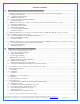
TABLE OF CONTENTS I. Motherboard preparation & water-block mechanical installation............................................................................................ 6 A. B. C. D. E. MCW5002-775T™ Thermoelectric Water-block Installation Guide for Intel® Pentium® 4 (LGA775) ....................................7 Preparing the motherboard......................................................................................................................................................
III. Periodic maintenance................................................................................................................................................................... 32 A. B. C. Keeping your system clean ...................................................................................................................................................32 Fluid Level..........................................................................................................................
Preamble Congratulations on your purchase of a Swiftech liquid cooling system! This kit has been designed to facilitate the installation of the components with as few and simple modifications to the chassis as possible. It is nonetheless intended for technically advanced users, well versed in installing computer components. General guidelines Never work with electricity connected to the computer while work is in progress. The reservoir should preferably be at the highest point of the cooling circuit.
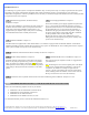
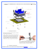
Installation Overview The following is a typical sequence of components installation. Step 1 is always first. Steps 2 to 6 may be performed out of sequence depending on the chassis configuration. Placement of the cooling components may also vary depending on your chassis and motherboard configurations. A mock-up installation is thus necessary to estimate the length of the different sections of tubing that will be required between each component.
1. MCW5002-775T™ THERMOELECTRIC WATER-BLOCK INSTALLATION GUIDE FOR INTEL® PENTIUM® 4 (LGA775) Figure 1 A. Preparing the motherboard Remove the stock heatsink retention mechanism to reveal the four-motherboard mounting holes. Install a standoff in each one of the holes. As the diameter of the mounting holes is usually larger than the diameter of the standoff stem, be careful to keep the standoff approximately centered in the MB holes.
The following instructions are crucial to long lasting & reliable operations. Do not skip these steps, and do not take shortcuts. Permanent damage to your components is likely to occur otherwise. C. Motherboard preparation Conformal coating application: This step will positively ensure that any micro condensation occurring on small surface mount components will not corrode or short-circuit the motherboard. Please use the enclosed conformal coating spray.
Step 4 7/ Squeeze a small amount of Céramique thermal compound on the CPU. 8/ Peel-off the protective paper from motherboard gasket #2 (1/8” thick) and carefully align the gasket over motherboard gasket #1, with the sticky side up Step 6 Step 5 9/ Align the water-block mounting posts with the motherboard standoffs, and tighten the screws in a cross pattern. Do not over-tighten the screws or they could jam into the standoffs, making further removal difficult.
2. MCW5002-PT™ THERMOELECTRIC WATER-BLOCK INSTALLATION GUIDE FOR INTEL® PENTIUM® 4 (SOCKET 478) Figure 1 A. Preparing the Motherboard Remove the stock heatsink retention frame (the black plastic frame that clips down to your motherboard). This will reveal the four mounting holes used to install the MCW5000-PT™ retention standoffs. Install a standoff in each one of the holes.
Use a ¼” socket tool to drive the standoff, and a small pair of pliers to prevent the locknut from spinning. Torque value should not to exceed 16 in. lbs. In other words JUST TIGHT, WITHOUT EXCESSIVE TORQUE. B. Condensation control measures The following instructions are crucial to long lasting & reliable operations. Do not skip these steps, and do not take shortcuts. Permanent damage to your components is likely to occur otherwise. C.
To complete the condensation prevention measures, simply apply the neoprene sticker provided with your MCW5002-PT™ accessories to the back of the motherboard, directly behind the processor. D. CPU and water-block installation Securing the MCW5002-PT cooler to the motherboard: Install the MCW5002-PT™ assembly onto your processor, as shown in figure 8. Gradually tighten the screws in a cross pattern until you feel that they reach the bottom of the standoff. A “finger-tight” lock is sufficient.
3. MCW5002-AT™ THERMOELECTRIC WATERBLOCK INSTALLATION GUIDE FOR AMD ATHLON MP, XP, SEMPRON (SOCKET 462 MOTHERBOARDS WITH MOUNTING HOLES EXCLUSIVELY) Figure 1 Preamble The following instructions are crucial to long lasting & reliable operations. Do not skip these steps, and do not take shortcuts. Permanent damage to your components is likely to occur otherwise. A.
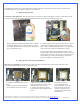
Figure 2 Spray the back of the motherboard, concentrating on the area immediately behind the CPU. Also spray all the way down, in a vertical path directly under the CPU area. Allow time to dry, per manufacturer specs. Figure 3 Use masking tape to protect the CPU socket, and any connector sockets in the immediate vicinity of the processor. A double layer of tape is recommended for all sockets, as the spray may soak a single layer of tape and contaminate the contacts.
Figure 6 Remove the peel-off paper back from the motherboard gasket, and install it as shown above. The sticky side should be towards the motherboard. Insert the processor into the socket. Since you have grease inside the socket, some hydraulic pressure lift may occur: for this reason, make sure that the processor sits perfectly flat, and is inserted all the way into the socket. Then, drop a small amount of high quality thermal compound into the center of the processor core.
4. MCW5002-64T™ THERMOELECTRIC WATER-BLOCK INSTALLATION GUIDE FOR AMD ATHLON 64, OPTERON (SOCKET 754, 939, 940) Figure 1 Preamble The following instructions are crucial to long lasting & reliable operations. Do not skip these steps, and do not take shortcuts. Permanent damage to your components is likely to occur otherwise. A.
Figure 2 Spray the back of the motherboard, concentrating on the area immediately behind the CPU. Also spray all the way down, in a vertical path directly under the CPU area. Allow time to dry, per manufacturer specs. Figure 3 Use masking tape to protect the CPU socket, and any connector sockets in the immediate vicinity of the processor. A double layer of tape is recommended for all sockets, as the spray may soak a single layer of tape and contaminate the contacts.
Part # AJ00264 backing plate alone Figure 6 Remove the peel-off paper back from the motherboard gasket, and install it as shown above. The sticky side should be towards the motherboard. Part # AJ00172 complete retention frame & backing plate Figure 7 Insert the processor into the socket. Since you have grease inside the socket, some hydraulic pressure lift may occur: for this reason, make sure that the processor sits perfectly flat, and is inserted all the way into the socket.
Type of Coolant: For best performance, use 5 to 10% of Swiftech brand “HydrX” corrosion inhibitor mixed with distilled water only . Regular automotive anti-freeze is also acceptable. Automotive manufacturers recommend that not less than 25% is used. NEVER use tap water, even for a short-term test. Not following the above instructions constitutes misuse (*) of the product, and will void your warranty. wires.
Figure 1 B. Relay Switch Installation Find a suitable placement to drill a hole for the A/C socket adapter. Leave sufficient room under or above the hole to install the relay switch circuit board. A ¼” minimum clearance will be required between the circuit board and the edge of the hole. 1.25" Hole A/C Socket Proceed with electrical connections as described in fig.
Relay switch connection diagram A/C Soc ket The relay switch and A/C socket adapter installed Relay switc h E N L N\O N\O + Ground + 12v WARNING! Always disconnect from A/C power source while working with electrical devices. L N Com puter Power Supply S320-12 Power supply Figure 4 Figure 3 C. Power Supply ventilation The following information is optional, and subject to existing ventilation in your particular chassis.
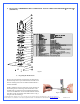
DOUBLE-CHECK DIMENSIONS PRIOR TO USING AS TEMPLATE Copyright Swiftech 2005 – All rights reserved – Last revision date: 12-27-05 - Information subject to change without notice – URL: http://www.swiftnets.com Rouchon Industries, Inc., dba Swiftech – 1703 E. 28th Street, Signal Hill, CA 90755 – Tel. 562-595-8009 – Fax 562-595-8769 - E Mail: Swiftech@swiftnets.
Another example of “blow-hole” installation Now that your power supply is physically in place, let’s move on to the installation of the next component. Note that connection of the TEC wires to the power supply will take place at the very end of the installation, once your hydraulic circuit has been leak proofed (chapter 2.7) 2. MCR220 RADIATOR INSTALLATION Preamble The MCR220™ dual 120mm radiator ships with the fans and the Radbox chassis already pre-assembled to the radiator.
o o o Exit cables and connectors from various PCI devices: the Radbox base plate can be moved in both vertical and horizontal directions to allow clearance for the cables. Opening the side panel once the Radbox is installed: the Radbox is supplied with various nylon spacers to separate the base plate from the surface of the back-panel and to provide clearance for opening of the side-panel. Note that a chassis with 80mm fan opening(s) is likely to provide a very good range of adjustments.
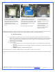
Once the two holes are cut, de-burr the edges, and install the grommets. Install your radiator assembly onto the back plate. Once the tubes are connected to the radiator, the final results will look like so: Remove the radiator assembly from the back-plate and mark the center of the circle. Two rubber grommets are provided with your kit so that you can route the tube though the case without damaging the tubing with the sharp edges of the hole. The required hole diameter for the grommet is 7/8” (23mm).
Example of Installation of the MCR220-QP radiator with Radbox 3. RE-INSTALLING THE MOTHERBOARD/WATER-BLOCK ASSEMBLY INTO THE CHASSIS Once your radiator and S320-12 power supply are in place, make sure to clean-off any metal shavings left inside the case, then go ahead and reinstall the motherboard/water-block assembly into the computer.
4. MCP655 PUMP INSTALLATION A. General Use Error! The MCP655 pump is a magnetically driven centrifugal pump featuring a 12 V DC motor. It requires no maintenance when used with de-mineralized water and the appropriate anti-fungal additives. We recommend using 5 to 10% of Swiftech’s HydrX™ as an additive. The pump is designed to be connected to your computer power supply using the standard Molex 4 pin connectors. The MCP655 pump is neither submersible, nor self- priming.
Copyright Swiftech 2005 – All rights reserved – Last revision date: 12-27-05 - Information subject to change without notice – URL: http://www.swiftnets.com Rouchon Industries, Inc., dba Swiftech – 1703 E. 28th Street, Signal Hill, CA 90755 – Tel. 562-595-8009 – Fax 562-595-8769 - E Mail: Swiftech@swiftnets.
5. MCRES-MICRO RESERVOIR INSTALLATION ITEM NO. 1 PART NUMBER MCRES-MICRO 2 1-4“ NPSM x 3-8“ and 1-2“barb 3 O-RING-9557K473 4 pg7-o-ring 5 pg7-plug 6 MOUNTING HARDWARE 6a DESCRIPTION Reservoir 1 Barb fitting 2 pairs each Barb fitting O-Ring 2 Fill-cap o-ring 1 Pg7 Fill-cap 1 3 90272A152-6-32x0500philips 6b 90760A007 6c washer-91007A614 6d WASHER-RUBBER-437X150X092 7 QTY. 6-32 x 7/8" (22mm) Philips screw 1 6-32 Nut 1 Lock Washer 1 Rubber Washer 1 panel 1 Figure 1 A.
• Two mounting methods can be used o o • Permanent mount with the provided mounting hardware as shown in figure 1. Three holes will need to be drilled for a permanent mount. Simply use the reservoir as a template to mark the hole locations, and use a 0.150” (4mm) drill bit to drill the holes. Make sure to clean up any metal shavings from the case once you are done. Easy mount, with the provided Velcro strips. This is a fairly secure mount, as we use extra strong Velcro.
Reservoir discharge to pump inlet Pump discharge to Radiator inlet Radiator discharge to CPU Water-block inlet CPU Water-block discharge to reservoir inlet Loop completed Connect the tube segments to the components, and secure them with the provided hose-clamps. E. Re-installing your computer power-supply Prior to fill-up the circuit, you will need to re-install your power-supply in order to start-up the pump during the fill procedure.
The TEC module is provided with “bare wires” to facilitate installation with screw type terminals such as featured in the S320-12 power supply Connect red wire from TEC module to the +V terminal, and black wire to the –V terminal as shown in figure 10 below Figure 10 A euro-style connector is provided with your kit in case you needed to extend the wires of the TEC to the power supply. Please only use 16 gage stranded wire.