H20-120T Thermoelectric LIQUID COOLING KITS TUTORIAL & INSTALLATION GUIDE These instructions are updated on a regular basis. Please visit our web site at http://www.swiftnets.com th Rouchon Industries, Inc., dbA Swiftech™ – 1703 E.
Packing List Included components per applicable model: H20-120-PT □ H20-120-775T □ H20-120-64T □ H20-120-AT □ Description Product Code PT 775T Intel Pentium 4 (socket 478) Intel Pentium 4 (LGA775) Product Code PT Qty 1 MCW5002-PT thermoelectric waterblock, with (2) # 6 worm drive hose clamps & gaskets 775T 1 64T 1 AT 1 ALL 1 ALL 1 ALL 1 Item Description AMDAthlon 64 (SOCKET 754, 939, 940) AMDAthlon MP, XP (socket 462) Product Code 64T AT Product Code ALL Qty Item 1 MCW5002-
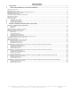
Table of contents I. II. TUBE ROUTING ......................................................................................................................................................................................................5 INSTALLATION OVERVIEW OF THE COOLING COMPONENTS ..................................................................................................................5 RADIATORS INSTALLATION.......................................................................................
Preamble Congratulations on your purchase of a Swiftech liquid cooling system! This kit has been designed to facilitate the installation of the components with as few and simple modifications to the chassis as possible. It is nonetheless intended for advanced users, well versed in installing computer components. General guidelines Never work with electricity connected to the computer while work is in progress. The reservoir should always be at the highest point of the cooling circuit .
I. TUBE ROUTING The following table contains examples on how to establish connections between the different elements of a cooling circuit This table assumes that the reservoir is positioned at the uppermost position in the computer, and that the pump is located at the lowermost location. These are guidelines only, and may change depending on the relative position of the components inside your chassis.
Cutting the tubing, & connecting components Now that your mock-up installation is in place, it is time to cut segments of tubing and connect the devices together. Preparing the coolant Your kit comes with a 2 Oz (60ml) bottle of Swiftech’s specially formulated HydrX concentrated coolant. The product should be mixed with distilled or demineralized water only. Simply empty the concentrated coolant into a 33 fl oz (1 liter) plastic bottle, and complete filling with your distilled water.
Figure 1 Figure 1 above illustrates a typical CPU cooling installation. Notice the use of Coolsleeves in very tight bends to prevent the tubes from kinking. Also note the position of the auxiliary power supply in the uppermost drive bay. Since this unit generates a significant amount of heat, a case with a blowhole on the top panel is desirable to reduce the overall internal case temperature.
III. Draining the system You will need to disconnect a line from one of the lowermost components. Procure a bucket large enough to receive approximately 1 liter of fluid, and place the bucket underneath the connection that you intend to “break”. Disconnect the line, and place both ends into the bucket. Open up the fill-cap from the MCRES-525. This will allow most of the fluid to escape.
V. Appendix: Individual Component Installation guides - INTENTIONNALY LEFT BLANK - th Rouchon Industries, Inc., dbA Swiftech™ – 1703 E.
Packing list MCR120 radiator 1 ½” barbs 2 Snap-rivet 6-32” x 3/8” Philips screw 4 4 120x25mm fan #6 worm drive clamps 1 2 Front of Chassis Snap-rivet 6-32 x 3/8" philips 120mm fan MCR120 radiator Figure 2 – Front of chassis installation Preamble The MCR120-F ships with the fan pre-assembled to the radiator. It has been configured so that the fan will draw fresh air from outside of the chassis. This configuration is preferred to optimize cooling of the CPU.
Rouchon Industries, Inc., dbA Swiftech™ – 1703 E.
1. General Use The MCP650 pump is a magnetically driven centrifugal pump featuring a 12 V DC motor. It requires no maintenance when used with demineralized water and the appropriate anti-fungal additives. We recommend using 5% Swiftech’s HydrX as an additive. The pump is designed to be connected to your computer power supply using the standard Molex 4 pin connectors. The MCP650 pump is not submersible. 2.
4. Performance & Specifications Nominal voltage 12 V DC Operating voltage range 6 to 14 VDC Nominal power (@ 12 V) 24 W Nominal current (@ 12 V) 2 amps Motor type Brushless, microprocessor controlled Maximum head 10 ft (3.1 m) Maximum discharge ~ 317 GPH (1200 LPH) Connection size ½" barbs Maximum pressure 50 PSI (3.5 BAR) Temperature range 32 °F to 140°F (0 °C to 60 °C) Electrical connector Molex 4 pin Weight 1.4 LB (650 gr.
PARTS LIST – Parts MCRES-525™ Reservoir Fill-cap & o-ring BARBED ADAPTERS ARE SOLD SEPARATELY QTY 1 1 PARTS Retention screws Port plug QTY 4 1 This product is intended for expert users. Please consult with a qualified technician for installation. Improper installation may result in damage to your components. Swiftech assumes no liability whatsoever, expressed or implied, for the use of these products, nor their installation. The following instructions are subject to change without notice.
Installation guidelines Figure 1: Always leave sufficient slack in the lines to pull enough of the reservoir out of the drive bay and uncover the fill port. Figure 2: You can start filling up the reservoir while it is in the drive bay, using a household funnel. Then, start-up the pump and top-off the reservoir as needed. With this method, you will be able to fill-up the reservoir to its minimum operating level, as shown figure 3. Figure 3: The minimum operating fluid level is at the mould parting line.
S320-12 Qty 1 1 1 1 1 1 This kit includes (Check-marked for applicable model and content): Item S320-12 power supply installed in 5 ¼” adapter tray, screws Electrical harness Relay Switch A/C socket adapter, stainless steel cover plate, screws A/C cord 80mm fan guard with (4) snap rivets Preamble This kit has been designed to facilitate installation with as little modifications to the case as possible. It is however meant for advanced users, well versed in installing computer components.
2. Relay Switch Installation Find a suitable placement to drill a hole for the A/C socket adapter. Leave sufficient room under or above the hole to install the relay switch circuit board. A ¼” minimum clearance will be required between the circuit board and the edge of the hole. Make a 1.25” (32mm) diameter hole in the case, using a 1 ¼” BiMetal hole saw. Deburr the edges of the hole with sand paper.
The template below provides holes dimensions for installation of such 80mm fan blowhole. A fan guard and snap rivets are provided with the kit to complete the installation. DOUBLE-CHECK DIMENSIONS PRIOR TO USING AS TEMPLATE th Rouchon Industries, Inc., dbA Swiftech™ – 1703 E.
Part MCW5002-775T assy. with TEC and gaskets 3/8” NPT to ½” barb fittings Motherboard installation hardware pack Qty 1 2 1 Part Céramique thermal compound Euro-style connector This product is intended for expert users only. Please consult with a qualified technician for installation. Improper installation may result in damage to your components. Swiftech assumes no liability whatsoever, expressed or implied, for the use of these products, nor their installation.
1. Preparing the motherboard Remove the stock heatsink retention mechanism to reveal the fourmotherboard mounting holes. Install a standoff in each one of the holes. As the diameter of the mounting holes is usually larger than the diameter of the standoff stem, be careful to keep the standoff approximately centered in the MB holes. Secure the standoffs with the provided hex locknuts, and a fiber washer on the backside of the MB as shown on fig. 1, using the tools described fig.
and remove the masking tape. Then let the board dry completely per manufacturer specs. b. CPU preparation & water-block installation Dielectric grease application: The following steps will ensure that condensation does not form inside of the CPU socket. Procure a tube of dielectric grease. We use Luberex grease, available on our web site here: http://www.swiftnets.com/store/category.
The TEC module is provided with “bare wires” to facilitate installation with screw type terminals such as featured in the S320-12 power supply Connect red wire from TEC module to the +V terminal, and black wire to the –V terminal as shown in figure 5. A complete installation guide for the S320-12 power supply kit is available here: http://www.swiftnets.com/products/installationguide_S320-12kit.
Part MCW5002-PT assy with TEC and gaskets 3/8” NPT to ½” barb fittings Motherboard installation hardware pack Qty 1 2 1 Part Arctic Alumina thermal compound Euro-style connector Qty 1 1 This product is intended for expert users only. Please consult with a qualified technician for installation. Improper installation may result in damage to your components. Swiftech assumes no liability whatsoever, expressed or implied, for the use of these products, nor their installation.
1. Preparing the motherboard Remove the stock heatsink retention frame (the black plastic frame that clips down to your motherboard). This will reveal the four mounting holes used to install the MCW5000-PT retention standoffs. Install a standoff in each one of the holes. As the diameter of the mounting holes is much larger than the diameter of the standoff stem, be careful to keep the standoff approximately centered in the MB holes.
• Dielectric grease application: This step will ensure that condensation does not form inside of the CPU socket. Procure a tube of dielectric grease. We use Luberex grease, available on our web site here: http://www.swiftnets.com/store/category.asp?CatID=11 Figure 5 Figure 6 Squirt a generous amount of grease onto the socket. Force the grease inside of the pin-holes with your finger. Make sure that the central area of the socket is completely filled with grease.
IMPORTANT WARNING: Solder joints of the wires to the thermoelectric module are extremely fragile. Bending the wires at their root will break the solder joint, with no possible repair. Swiftech will not honor the warranty for broken wires. a. Recommended installation: Connecting to a dedicated auxiliary power supply Minimum requirements for a dedicated power supply are 25A @ +12V. Your TEC module has been measured to draw 18 amps at 12 volts.
Type of Coolant: For best performance, use 95% distilled water, and 5% Swiftech brand “HydrX” corrosion inhibitor (available here: http://www.swiftnets.com/store/category.asp?CatID=2, under the “accessories” section). In all cases, you must use Distilled water and a corrosion inhibitor with the MCW5002 water-block. Regular automotive anti-freeze is acceptable. Automotive manufacturers recommend that not less than 25% is used. NEVER use tap water, even for a short-term test.
Part MCW5002-AT assy with TEC and gaskets 3/8” NPT to ½” barb fittings Qty 1 2 Part Arctic Alumina thermal compound Euro-style connector Qty 1 1 This product is intended for expert users only. Please consult with a qualified technician for installation. Improper installation may result in damage to your components. Swiftech assumes no liability whatsoever, expressed or implied, for the use of these products, nor their installation. The following instructions are subject to change without notice.
1. Condensation control measures The following instructions are crucial to long lasting & reliable operations. Do not skip these steps, and do not take shortcuts. Permanent damage to your components is likely to occur otherwise. a. Motherboard preparation • Conformal coating application: This step will positively ensure that any micro condensation occurring on small surface mount components will not corrode or short-circuit the motherboard. Procure a spray can of silicone conformal coating. We use M.G.
Figure 4 Figure 5 Squirt a generous amount of grease onto the socket. Force the grease inside of the pin-holes with your finger. Make sure that the central area of the socket is completely filled with grease. b.
Figure 8 Installation of the cooler to the motherboard is now complete! 2. Electrical Installation IMPORTANT WARNING: Solder joints of the wires to the thermoelectric module are extremely fragile. Bending the wires at their root will break the solder joint, with no possible repair. Swiftech will not honor the warranty for broken wires. a. Recommended installation: Connecting to a dedicated auxiliary power supply Minimum requirements for a dedicated power supply are 25A @ +12V.
b. Connecting to your computer power supply: Important Warning: to connect the MCW5002-ATcooler to an ATX computer power supply, you must carefully consider the existing requirements of other devices connected on the +12V line. Connecting to an underpowered unit will definitely damage the power supply. c. Connecting TEC wires to the power supply: Use the provided euro-style wire connector as shown in fig 11 below, or a similar device with a current rating of at least 25 amps.
Part MCW5002-64T assy with TEC and gaskets 3/8” NPT to ½” barb fittings Qty 1 2 Part Arctic Alumina thermal compound Euro-style connector Qty 1 1 This product is intended for expert users only. Please consult with a qualified technician for installation. Improper installation may result in damage to your components. Swiftech assumes no liability whatsoever, expressed or implied, for the use of these products, nor their installation. The following instructions are subject to change without notice.
1. Condensation control measures The following instructions are crucial to long lasting & reliable operations. Do not skip these steps, and do not take shortcuts. Permanent damage to your components is likely to occur otherwise. a. Motherboard preparation Conformal coating application: This step will positively ensure that any micro condensation occurring on small surface mount components will not corrode or short-circuit the motherboard. Procure a spray can of silicone conformal coating. We use M.G.
Figure 4 Figure 5 Squirt a generous amount of grease onto the socket. Force the grease inside of the pin holes with your finger. Make sure that the central area of the socket is completely filled with grease. c. CPU and cooler installation: Preamble: The MCW5002-64T requires the AMD recommended motherboard backing plates (made out of metal) for its installation.
it as shown above. The sticky side should be towards the motherboard. Since you have grease inside the socket, some hydraulic pressure lift may occur: for this reason, make sure that the processor sits perfectly flat, and is inserted all the way into the socket. Then, drop a small amount of high quality thermal compound into the center of the processor core.
time, it is also a good practice to setup an alarm temperature, which will shut down the computer in case the CPU overheats. Such alarm/shut down process should be tested as functional. WARNING! Wires from the thermoelectric module do get hot (this is normal). Make sure that the wires do not touch devices that are heat sensitive, such as vinyl tubes for example. Heat from the wires may cause the vinyl to deform, and/or burst. Figure 10 b.