These instructions are updated on a regular basis. Please visit our web site at http://www.swiftnets.com Copyright Swiftech 2007 – All rights reserved – Last revision date: 1-15-07 - Information subject to change without notice – URL: http://www.swiftech.com Rouchon Industries, Inc., dba Swiftech – 3400 Industry ave., suite 104, Lakewood, CA 90712 – Tel. 562-595-8009 – Fax 562-595-8769 - E Mail: help@swiftnets.
Packing List QTY 1 1 1 1 8 1 1 1 ITEM APOGEE GT water-block, including hold-down plates (multi sockets and AM2), various processors mounting systems, 3/8” barbs and hose clamps MCRES-Micro reservoir assembly, including mounting hardware 3/8” barbs and hose clamps MCP350 Pump, including mounting hardware, gaskets and (2) hose clamps MCR120 Radiator assembly, including pre-installed 120mm fan without fan guards, mounting hardware, (1) 12v to 7v adapters, (1) 12v to 5v 3-pin to 4-pin Molex adapters, (2) ho
TABLE OF CONTENT I. TUBE ROUTING ...........................................................................................................................5 II. INSTALLATION OF THE COOLING COMPONENTS ..................................................................6 1 MCR120-F Radiator installation ..................................................................................................................................................6 Internal radiator installation .....................
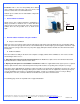
INTRODUCTION Congratulations on your purchase of a Swiftech™ H20-120 PREMIUM Liquid Cooling System! This kit has been designed to facilitate the installation of the components without having to make any modifications to the chassis. While all attempts have been made to make the installation of this system user friendly, please note that this system is intended for users that are well versed in installing computer components.
I. TUBE ROUTING The tubing for the water-cooling system must be routed to form a complete loop that includes all elements of the system. When daisy-chaining components, the simplest and most natural route is usually the best. Always avoid sharp bends that would kink the tubing! The following table contains examples on how to establish connections between the different elements of a cooling circuit based on multiple possible configurations.
VGA Cooler discharge to chipset cooler inlet Chipset cooler discharge to radiator (2) inlet Radiator (2) discharge to CPU cooler inlet CPU cooler discharge to reservoir inlet II. INSTALLATION OF THE COOLING COMPONENTS Placement of the cooling components may vary depending on your chassis and motherboard configurations. The following is the recommended sequence of components installation.
Cosmetics: This is the last and probably most difficult choice. Swiftech cannot presume of the user’s tastes, and therefore cannot make a recommendation here. Swiftech pre-assembles the fan and Radbox components to the radiator. Internal radiator installation Strictly from a CPU cooling performance standpoint it is always preferable to install the fan so that it will either draw or push fresh air from outside of the chassis into the radiator.
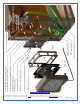
Exploded view of an installation Copyright Swiftech 2007 – All rights reserved – Last revision date: 1-15-07 - Information subject to change without notice – URL: http://www.swiftech.com Rouchon Industries, Inc., dba Swiftech – 3400 Industry ave., suite 104, Lakewood, CA 90712 – Tel. 562-595-8009 – Fax 562-595-8769 - E Mail: help@swiftnets.
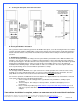
A. Securing the base plate at the desired location: B. Housing/Fan/Radiator installation Once you have found a satisfactory position for the Radbox base plate, secure the housing and fan to the radiator using the provided (4) M3.5 x 30mm Philips screws. Ensure that the exit of the fan wire is positioned towards the bottom of the PC and to its left (towards the motherboard) to facilitate further routing of the wire through the PCI pass-thru. C.
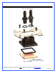
2 APOGEE GT WATER-BLOCK INSTALLATION One or more Patents pending Figure 1 – Exploded View Copyright Swiftech 2007 – All rights reserved – Last revision date: 1-15-07 - Information subject to change without notice – URL: http://www.swiftech.com Rouchon Industries, Inc., dba Swiftech – 3400 Industry ave., suite 104, Lakewood, CA 90712 – Tel. 562-595-8009 – Fax 562-595-8769 - E Mail: help@swiftnets.
Packing List COMPONENT ID BHSC006C0-007SS O-RING 3/32 APOGEE-H APOGEE-BRKT APOGEE-BP B1000-2.5X50 PM4S-6BN PM4S-8BN 22HC04688 22HC0672B SPRING6 6-32 HEX CAP 12SWS0444 LOCKWASHER6 FW140X250X0215FB BLK 632.112PHPMS 6-32 NUT 6-32 X 1 5/8 WASHER-0148X0266X0040-91007A619 90272A153-6-32X1.
Intel® Pentium® 4 Socket 478 Intel® Pentium® 4 Socket 478 Use hardware from the “common pack” ITEM NO. PART NUMBER 1 S478 2 apogee-assy APOGEE-H APOGEE-BP APOGEE-BRCKT O-RING-9557K473 1-4-straightx3-8-barb APOGEE-P4S478--HARDWARE 6-32-Acorn-nut 70927-368 6-32-nut LOCK-WASHER#6 FW140X250X0215FB BLK 91772A157-6-32x1.
Intel® Pentium® 4 and Pentium® D Socket LGA 775 Intel® Pentium® 4 and Pentium® D Socket LGA 775 Use hardware from the “common pack” ITEM NO. 1 2 2a 2b 3 3a 3b 3c 3d 3e 3f 3g 2b PART NUMBER LPGA 775 apogee-assy 92949A149 O-RING-9557K473 1-4-straightx3-8-barb O-RING_3-32 APOGEE-H APOGEE-BP APOGEE-BRCKT APOGEE-775-HARDWARE 6-32-Acorn-nut SPRING6 6-32-nut LOCK-WASHER#6 FW140X250X0215FB BLK 91772A157-6-32x1.5 12SWS0444 DESCRIPTION QTY.
Intel® Xeon™ Socket 604 & 771 800 MHz FSB motherboards Intel® Xeon™ Socket 604 “Nocona” 800 MHz FSB motherboards Use Intel Xeon “Nocona” separate hardware. ITEM NO. PART NUMBER 1 Nocona board mockup 2 spring-backplate 3 4 chassis STANDOFF-0.187 4-40 nylon retaining washer 5 SPACER-13LTS2501400697 3a 6 90272A153-6-32x1-philips 7 apogee-assy APOGEE-H APOGEE-BP APOGEE-BRCKT O-RING-9557K473 1-4-straightx3-8-barb 7a 7b DESCRIPTION QTY.
Intel® Xeon™ Socket 603/604 400 and 533 MHz FSB motherboards Intel® Xeon™ Socket 603/604400 and 533 MHz FSB motherboards Use all parts from “common parts pack” except Philips screws: replace with the enclosed 6-32 1 5/8” long screws, instead of the 1 1/2” long screws supplied in the common parts pack. ITEM NO.
AMD® Athlon®, Duron®, MP, XP, Sempron® Socket 462 AMD® Athlon®, Duron®, MP, XP, Sempron® Socket 462 Use common hardware pack. Compatibility: Exclusively compatible with motherboards featuring mounting holes around the socket. ITEM NO. 1 2 2a 2b 3 3a 3b 3c 3d 3e 3f 3g PART NUMBER socket462 apogee-assy 92949A149 O-RING-9557K473 1-4-straightx3-8-barb APOGEE-H APOGEE-BP APOGEE-BRCKT APOGEE-462-HARDWARE 6-32-Acorn-nut SPRING6 6-32-nut LOCK-WASHER#6 FW140X250X0215FB BLK 91772A157-6-32x1.
AMD® 64, Sempron®, Opteron® Socket 754, 939, 940 AMD® 64, Sempron®, Opteron® Socket 754, 939, 940 Use separate AMD 754/939/940 hardware pack ITEM NO. 1 2 PART NUMBER 90272A153-6-32x1.00-philips washer-0148x0266x0040-91007A619 3 4 13RS040637 AJ00264 5 6 1-4-NPSMx3-8-barb O-RING-9557K473 DESCRIPTION 6-32 x 1" Philips screw QTY . 2 Lock Washer #6 x 0.
AMD® 64, FX, X2, Sempron®, Socket AM2 AMD 64, FRX, X2, Sempron, Socket AM2 The Apogee water-block ships pre-installed with the multi-socket hold-down plate. In order to install your Apogee with AMD’s AM2 socket, you will need to remove the existing hold-down plate first and replace it with the AM2 model as follows: Step 1: loosen all 4 screws using the included hex key, and set aside the standard hold-down plate.
ITEM PART NUMBER 1 90272A153-6-32x1.00-philips 2 washer-0148x0266x0040-91007A619 3 apogee-assy-AM2 4 13RS040637 5 SOCKET AM2 DESCRIPTION QTY . Philips screw 4 Lock Washer #6 x 0.040 4 1 Nylon spacer for Apogee K8 assy 4 1 1 2 3 4 5 Copyright Swiftech 2007 – All rights reserved – Last revision date: 1-15-07 - Information subject to change without notice – URL: http://www.swiftech.com Rouchon Industries, Inc., dba Swiftech – 3400 Industry ave., suite 104, Lakewood, CA 90712 – Tel.
3 MCRES-MICRO RESERVOIR INSTALLATION ITEM NO. PART NUMBER DESCRIPTION QTY.
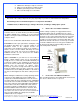
Product Description The MCRES-MICRO is a small form factor reservoir designed for liquid-cooled personal computers. The device features two 1/4” NPSM threaded ports and a Pg7 fill-port The port usage is defined as follows: Upper port: “In from system” shown in figure 1 is the return line from the system Lower port: “Out to pump inlet” shown in figure 1 should be connected to the pump inlet. The fill-port located on top of the unit is used to fill it up with coolant, and sealed with a Pg7 plug.
MCRes Micro Bracketry installation and examples 6 7 5 ITEM NO. PART NUMBER 1 2 BCKT1 BCKT2 90272A146-6-32x3-8-philips 3 4 5 DESCRIPTION QTY . 1 "L" bracket "U" bracket 2 6-32 Nut w/teeth washer 3 2 3 6 FW150X437X092 Rubber Washer 437X150X092 2 7 93286A041-WASHER zinc plated washer 5 91772A158-6-32X1.75 90760A007 6-32 x 3/8” Philips screw 6-32 x 1 3/4" Philips screw Note 1: rubber washer 6 should be inserted between either side of the reservoir ear and the U bracket 2.
4 MCP350 PUMP INSTALLATION General Use The MCP350™ pump is a magnetically driven centrifugal pump featuring a 12 V DC brushless motor. It requires no maintenance when used with de-mineralized water and the appropriate anti-fungal additives. We recommend using 5 to 10% Swiftech’s HydrX™ as an additive.
Permanent Installation Drill two 0.312” (8mm) holes into panel, 2.52” (64mm) apart. Snap grommet into each hole. Tighten the provided screws until the pump neoprene pad is slightly and evenly compressed by approximately 1/8” (2~3mm) or less. Exploded view Performance & Specifications Nominal voltage 12 V DC Operating voltage range 9 to 13.2 VDC Nominal power (@ 12 V) 8.3 W Nominal current (@ 12 V) .
6 PREPARING THE TUBING Now that your radiator, water-block, pump and reservoir are ready, it is time to cut segments of tubing and connect the elements of the cooling system together. In addition to the supplied high quality vinyl tubing, your kit also comes with a 40” length of Smartcoils which, when extended provides a sufficient length to wrap 6 feet of tubing. Use of these coils is mandatory in order to prevent kinking and flattening of the tube over time.
7 PREPARING THE COOLANT Your kit comes with a 2 Oz (60ml) bottle of Swiftech’s specially formulated HydrX™ concentrated coolant. The product should be mixed with distilled water only. Simply empty the concentrated coolant into a 33 fl oz (1 liter) plastic bottle, and complete filling with distilled water. Your coolant is now ready. Note: a 5% mix might still allow some algae formation over prolonged usage if your system is continuously exposed to daylight (such as a clear acrylic case for example).
10 COMPLETING THE INSTALLATION Once your system has been fully tested for leaks, you may complete all the electrical and data connections to the motherboard, Hard Drives, CD Roms, etc.. INSTALLATION COMPLETE! III. DRAINING THE SYSTEM • • • • Disconnect the PC from AC power You will need to disconnect a line from one of the lowermost components. Procure a bucket large enough to receive approximately 1 liter of fluid, and place the bucket underneath the connection that you intend to “break”.
Add a second Apogee water block for multiprocessor applications, such as dual AMD®, dual Xeon™, or dual Opteron™ Cool the chipset with the MCW30 chipset cooler For Dual Xeon “Nocona” users do not forget to add the optional Nocona hardware (part AP-NC604) when you purchase your second Apogee water-block. In effect, while this hardware is included in this kit, it is not included when the Apogee water-block is sold separately. Cool the VGA memory with the MCW-Ramcool Go to: http://www.swiftech.