These instructions are updated on a regular basis. Please visit our web site at http://www.swiftnets.com Copyright Swiftech 2005 – All rights reserved – Last revision date: 09-22-06 - Information subject to change without notice – URL: http://www.swiftnets.com th Rouchon Industries, Inc., dba Swiftech – 1703 E. 28 Street, Signal Hill, CA 90755 – Tel. 562-595-8009 – Fax 562-595-8769 - E Mail: Swiftech@swiftnets.
Packing List QTY 1 1 1 8 1 1 1 ITEM APOGEE water-block, including hold-down plates (multi sockets and AM2), various processors mounting systems, and (2) hose clamps MCRES-1000P pump & reservoir 5 ¼” bay assembly, including mounting hardware and (2) ½” hose clamps MCR120 Radiator assembly, including pre-installed 120mm fan without fan guards, mounting hardware, (1) 12v to 7v adapters, (1) 12v to 5v 3-pin to 4-pin Molex adapters, (2) hose clamps, and MCB-120 Radbox, with mounting hardware Feet 3/8” (tube
TABLE OF CONTENT I. TUBE ROUTING ............................................................................................................................................................. 5 II. INSTALLATION OF THE COOLING COMPONENTS ................................................................................................... 5 1 MCR120-F RADIATOR INSTALLATION ........................................................................................................................................
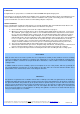
INTRODUCTION Congratulations on your purchase of a Swiftech™ H20-120 PREMIUM Liquid Cooling System! This kit has been designed to facilitate the installation of the components without having to make any modifications to the chassis. While all attempts have been made to make the installation of this system user friendly, please note that this system is intended for users that are well versed in installing computer components.
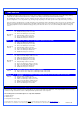
I. TUBE ROUTING The tubing for the water-cooling system must be routed to form a complete loop that includes all elements of the system. When daisy-chaining components, the simplest and most natural route is usually the best. Always avoid sharp bends that would kink the tubing! The following table contains examples on how to establish connections between the different elements of a cooling circuit based on multiple possible configurations.
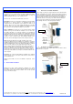
1 MCR120-F RADIATOR INSTALLATION Your first choice is to decide whether you will be installing the radiator INSIDE of the computer, or use the included “Radbox” to hang the radiator OUTSIDE at the back of the computer chassis.
External radiator installation using the “Radbox” PCI pass-thru Installation Make sure to insert your fan electrical connector through the slotted hole of the PCI bracket before you install the tubing. Only 3-pin connectors (the type that connect to the motherboard) are small enough to pass through the slotted hole. 4-pin Molex connectors (the type that connect to your power supply) will require that the terminals be removed from the Molex housing first.
Exploded view of an installation Copyright Swiftech 2005 – All rights reserved – Last revision date: 09-22-06 - Information subject to change without notice – URL: http://www.swiftnets.com th Rouchon Industries, Inc., dba Swiftech – 1703 E. 28 Street, Signal Hill, CA 90755 – Tel. 562-595-8009 – Fax 562-595-8769 - E Mail: Swiftech@swiftnets.
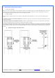
B. Housing/Fan/Radiator installation Once you have found a satisfactory position for the Radbox base plate, secure the housing and fan to the radiator using the provided (4) M3.5 x 30mm Philips screws. Ensure that the exit of the fan wire is positioned towards the bottom of the PC and to its left (towards the motherboard) to facilitate further routing of the wire through the PCI pass-thru. C. Finalizing the installation Secure the housing/fan/radiator assembly to the base plate with the provided #4 screws.
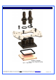
2 APOGEE WATER-BLOCK INSTALLATION One or more Patents pending Figure 1 – Exploded View Copyright Swiftech 2005 – All rights reserved – Last revision date: 09-22-06 - Information subject to change without notice – URL: http://www.swiftnets.com th Rouchon Industries, Inc., dba Swiftech – 1703 E. 28 Street, Signal Hill, CA 90755 – Tel. 562-595-8009 – Fax 562-595-8769 - E Mail: Swiftech@swiftnets.
Packing List COMPONENT ID COMPONENT DESCRIPTION QTY USAGE BHSC006C0-007SS 6-32 X 7/16 BUT HD CAP SS 4.00 WATER-BLOCK ASSEMBLY O-RING 3/32 B1000-133 O-RING 3/32 X 1 13/1 1.00 WATER-BLOCK ASSEMBLY APOGEE-H APOGEE WATERBLOCK HOUSING 1.00 WATER-BLOCK ASSEMBLY APOGEE-BRKT APOGEE HOLD-DOWN PLATE 1.00 WATER-BLOCK ASSEMBLY APOGEE-BP B1000-2.5X50 APOGEE BASE PLATE BUNA-N 70D BLACK O-RING 1.00 2.00 WATER-BLOCK ASSEMBLY FITTINGS PM4S-6BN 1/4" - 1/8 NPSM TO 3/8" ID 2.
Intel® Pentium® 4 Socket 478 Intel® Pentium® 4 Socket 478 Use hardware from the “common pack” ITEM NO. PART NUMBER 1 S478 2 apogee-assy APOGEE-H APOGEE-BP APOGEE-BRCKT O-RING-9557K473 1-4-straightx3-8-barb APOGEE-P4S478--HARDWARE 6-32-Acorn-nut 70927-368 6-32-nut LOCK-WASHER#6 FW140X250X0215FB BLK 91772A157-6-32x1.
Intel® Pentium® 4 and Pentium® D Socket LGA 775 Intel® Pentium® 4 and Pentium® D Socket LGA 775 Use hardware from the “common pack” ITEM NO. 1 2 2a 2b 3 3a 3b 3c 3d 3e 3f 3g 2b PART NUMBER LPGA 775 apogee-assy 92949A149 O-RING-9557K473 1-4-straightx3-8-barb O-RING_3-32 APOGEE-H APOGEE-BP APOGEE-BRCKT APOGEE-775-HARDWARE 6-32-Acorn-nut SPRING6 6-32-nut LOCK-WASHER#6 FW140X250X0215FB BLK 91772A157-6-32x1.5 12SWS0444 DESCRIPTION QTY.
Intel® Xeon™ Socket 604 “Nocona” 800 MHz FSB motherboards Intel® Xeon™ Socket 604 “Nocona” 800 MHz FSB motherboards Use Intel Xeon “Nocona” separate hardware. ITEM NO. PART NUMBER 1 Nocona board mockup 2 spring-backplate 3 4 chassis STANDOFF-0.187 4-40 nylon retaining washer 5 SPACER-13LTS2501400697 6 90272A153-6-32x1-philips 7 apogee-assy APOGEE-H APOGEE-BP APOGEE-BRCKT O-RING-9557K473 1-4-straightx3-8-barb 3a 7a 7b DESCRIPTION QTY.
Intel® Xeon™ Socket 603/604 400 and 533 MHz FSB motherboards Intel® Xeon™ Socket 603/604400 and 533 MHz FSB motherboards Use all parts from “common parts pack” except Philips screws: replace with the enclosed 6-32 1 5/8” long screws, instead of the 1 1/2” long screws supplied in the common parts pack. ITEM NO.
AMD® Athlon®, Duron®, MP, XP, Sempron® Socket 462 AMD® Athlon®, Duron®, MP, XP, Sempron® Socket 462 Use common hardware pack. Compatibility: Exclusively compatible with motherboards featuring mounting holes around the socket. ITEM NO. 1 2 2a 2b 3 3a 3b 3c 3d 3e 3f 3g PART NUMBER socket462 apogee-assy 92949A149 O-RING-9557K473 1-4-straightx3-8-barb APOGEE-H APOGEE-BP APOGEE-BRCKT APOGEE-462-HARDWARE 6-32-Acorn-nut SPRING6 6-32-nut LOCK-WASHER#6 FW140X250X0215FB BLK 91772A157-6-32x1.
AMD® 64, Sempron®, Opteron® Socket 754, 939, 940 AMD® 64, Sempron®, Opteron® Socket 754, 939, 940 Use separate AMD 754/939/940 hardware pack ITEM NO. 1 2 3 4 5 6 PART NUMBER 90272A153-6-32x1.00-philips washer-0148x0266x0040-91007A619 13RS040637 AJ00264 1-4-NPSMx3-8-barb O-RING-9557K473 DESCRIPTION 6-32 x 1" Philips screw Lock Washer #6 x 0.040 QTY .
AMD® 64, FX, X2, Sempron®, Socket AM2 Remove the pre-installed hold-down plate first, as described on the next page. ITEM PART NUMBER 1 90272A153-6-32x1.00-philips 2 washer-0148x0266x0040-91007A619 3 apogee-assy-AM2 4 13RS040637 5 SOCKET AM2 DESCRIPTION QTY . Philips screw 4 Lock Washer #6 x 0.
The Apogee water-block ships pre-installed with the multi-socket hold-down plate. In order to install your Apogee with AMD’s AM2 socket, you will need to remove the existing hold-down plate and replace it with the AM2 model as follows: Step 1: loosen all 4 screws using the included hex key, and set aside the standard hold-down plate. Step 2: place the AM2 hold-down plate on the Apogee body, and fasten all four screws in cross pattern. You can now use your Apogee with AM2 socket.
3 PREPARING THE TUBING Now that your radiator, water-block, pump and reservoir are in place, it is time to cut segments of tubing and connect the devices together. In addition to the supplied high quality vinyl tubing, your kit also comes with a 40” length of Smartcoils which, when extended provides a sufficient length to wrap 6 feet of tubing. Use of these coils is mandatory in order to prevent kinking and flattening of the tube over time.
4 MCRES-1000P ASSEMBLY INSTALLATION Introduction The radiator inlet and outlet spigots must be oriented upwards during the filling procedure. If you are using the Radbox, and already fastened the radiator/fan/Radbox housing to the Radbox base plate, go ahead and dismount the assembly and let the radiator/fan/housing assembly hang down over your bench table as shown in the picture paragraph B step1. Generally speaking proceed deliberately and frequently check your work.
TIP! If you overfill the reservoir, you can use a bundled-up paper towel to soak-up the excess fluid. Step 4. Tilt the assembly upwards to allow the fluid to fill-up the circuit by simple gravity. Allow the fluid to fill-up both tubes. The pump discharge line will retain a 2” long bubble, which is normal at this stage. See troubleshooting note (1) if the pump discharge tube does not fill-up properly. Step 5.
B. Alternate filling procedure The following filling procedure applies to situations where the reservoir must be or is already installed inside of the CD-Rom bay. Please refer to steps 1, and 2 (paragraph A) above for physical connections and installation in the CD-Rom drive Bay. Step 1. Radiator inlet and outlet should always be oriented upwards during the filling procedure. In the above picture, the MCB-120 Radbox conveniently allows you to let the radiator fan assembly hang from your workbench.
Step 6. Bring the PC back up as shown in step 3 above (keep it angled at 15 to 20°), and complete filling-up the reservoir as necessary, and then close the fill port. Complete the installation by securing the MCRES-1000 in the CD-Rom bay with the provided M3 screws, as shown in step 8, paragraph A. YOUR SYSTEM IS NOW READY TO USE! ALLOW THE SYSTEM TO RUN FOR (3) HOURS, AND FREQUENTLY INSPECT ALL YOUR CONNECTIONS FOR POSSIBLE LEAKS BEFORE YOU RECONNECT YOUR COMPONENTS (MOTHERBOARD, HARD DRIVES, ETC.
7 COMPLETING THE INSTALLATION Once your system has been tested for leaks, it is now time to finalize the water-block and components installation. Do not forget to remove the protective paper you used to protect the CPU and water-block. Follow the instructions listed in the Apogee installation section to secure your water-block(s) to the motherboard, and then re-install your components inside of the chassis. Ideal high overall performance installation (with “Radbox”) III.
V. Add-on components Improve performance with a second radiator: MCR120-FK Radiator assembly Cool your graphics card with the MCW55 VGA water-block. Go to: http://www.swiftnets.com/products/mcw55.