IEEE 802.11g Wireless Router User’s Manual Version 1.
Trademarks Microsoft, Windows, and Windows NT are registered trademarks of Microsoft Corporation. Other brand and product names are registered trademarks or trademarks of their respective holders. Statement of Conditions In the interest of improving internal design, operational function, and/or reliability, we reserves the right to make changes to the products described in this document without notice.
About This User Manual Welcome to the Networking world of the Wireless Router! This manual is intended as a basic introduction to your Wireless Router. It provides enough information to make the Router operational in most common environments: connecting to the Internet, create your own private network and share an Internet connection. We'll describe how to use your web browser to configure the Router and to perform some basic operations, e.g.
Contents Chapter 1-Introduction Overview of the 802.
Firewall - DMZ (Demilitarized Zone) Appendix A Troubleshooting Appendix B Specifications 40 41 42 4 802.
Chapter 1: Introduction Overview of the 802.11g Wireless Router The model WF514 802.11g Wireless Router with 4-port switch connects your local area network (LAN) to the Internet. The WF514 is a multi-function device. First, there is the Wireless Access Point, which lets you connect 802.11g or 802.11b equipped devices to the network. There is also a built-in 4-port 10/100 Ethernet Switch to connect your wired-Ethernet devices.
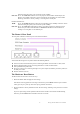
LED does not light up, then your connection speed is 10Mbps. Link/ACT Green. The Link /ACT LED also serves two purposes. If the LED is continuously lit, the Router is successfully connected to a device through the corresponding port. If the LED is flickering, the Router is actively sending or receiving data over that port. EWAN LED Indicators: 10/100 Green. The 10/100 LED lights up when the corresponding port is 100Mbps connection. If this LED does not light up, then your connection speed is 10Mbps.
Chapter 2: Connecting the Router This chapter describes how to connect the Router to your local area network (LAN). You will have to configure your networked PCs to accept the IP addresses that the Router assigns them, and you will also have to configure the Router with settings provided by your Internet Service Provider (ISP). The installation technician from your ISP should have left the setup information for your modem with you after installing your broadband connection.
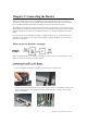
3. Connect a different Ethernet cable from your Cable or DSL modem to the EWAN port on the rear of the Router. Modem 4. Power on all of your PCs. If all of your Link LEDs are not lighting up, make sure that all your cables are securely plugged in, and that all of your hardware is powered on properly. Connecting wireless PC to the Router Follow these steps to connect wireless PC to the Router. 1. 2. 3. 4. Power on the Router and modem, and make sure all of your PCs are powered off.
Chapter 3: Configuring the PCs This chapter describes how to configure each of your PCs to be able to communicate with the Router. To do this, you need to configure your PC’s network settings to obtain an IP address automatically, so your PC can function as a DHCP client. Configuring Windows 98 and Windows Me PCs 1. Click the Start button, select Settings and then Control Panel. Double-click the Network icon. 2. On the Configuration tab, select the TCP/IP line for the applicable Ethernet adapter.
4. 5. 6. Click the Gateway tab, and verify that the Installed Gateway field is blank. Click the OK button. Click the OK button again. Windows may ask you for the original Windows installation CD or additional files. Check for the files at c:\windows\options\cabs, or insert your Windows CD-ROM into your CD-ROM drive and check the correct file location, e.g., D:\win98 (if “D” is the letter of your CD-ROM drive). Windows may ask you to restart your PC. Click the Yes button.
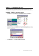
1 2 (TCP/IP) 3 4. Select Obtain an IP address automatically and Obtain DNS server address automatically. Once the new window appears, click the OK button. Click the OK button again to complete the PC configuration. 1 2 3 5. Restart your PC. Go to “Chapter 4: Configuring the Router” Configuring Windows XP PCs 1. Click the Start button, select Settings and then Control Panel. Double-click the Network Connections icon. 11 802.
2. 3. Select the Local Area Connection icon for the applicable Ethernet adapter. Right-click the Local Area Connection, then click the Properties option. Make sure the box next to Internet Protocol (TCP/IP) is checked. Highlight Internet Protocol (TCP/IP), and click the Properties button. 2 (TCP/IP) 1 4. 3 Select Obtain an IP address automatically and Obtain DNS server address automatically. Once the new window appears, click the OK button. Click the OK button again to complete the PC configuration.
1 2 3 Go to “Chapter 4: Configuring the Router” 13 802.
Chapter 4: Configuring the Router Once you have completed all the hardware installation and have configured your PCs properly as described in chapter three, you are ready to configure the Router for actual applications. The instructions from your ISP tell you how to set up your PC for Internet access. Because you are now using the Router to share Internet access among several PCs, you will use the setup information to configure the Router instead of your PC.
User name: admin Password: 1234 4. Select the time zone for your location. If your location experiences daylight saving, check the box next to Daylight Saving. Click NEXT button. 5. Based on the setup instructions from your ISP, you need to select one of WAN connection types. The Router supports four connection types: PPPoE, PPTP, Static IP Address, and Dynamic IP Address. Each setup screen and available features will differ depending on what kind of connection type you select. 15 802.
PPPoE If your DSL provider says that you are connecting through PPPoE, perform these steps: a. Enter the User Name b. Enter the Password c. Reenter the password d. Enter the Service Name if your ISP requires it. This is optional. e. Keep the value of MTU as default setting. Note: MTU (Maximum Transmission Unit) is the largest frame size that can be transmitted over the network. Messages longer than the MTU must be divided into smaller frames. f.
PPTP Point to Point Tunneling Protocol (PPTP) is a service that applies to connections in Europe only. If your DSL provider says that you are connecting through PPTP, perform these steps: a. b. c. d. e. f. g. h. i. j. k. Enter the PPTP Account Enter the PPTP Password Reenter the PPTP Password Enter the Host Name if your ISP requires it. Enter Service IP Address. Your ISP will provide you with the Service IP Address. Enter My IP Address. This is the Router’s IP address, when seen from the Internet.
Static IP Address If you are required to use a permanent IP address to connect to the Internet, then select Static IP Address. a. Enter the IP address assigned by your ISP. This is the Router’s IP address, when seen from the Internet. Your ISP will provide you with the IP address you need to specify here. b. Enter Subnet Mask. This is the Router’s subnet mask, as seen by external users on the Internet. Your ISP will provide you with the subnet mask. c. Enter ISP Router Address.
6. If your ISP will automatically assign DNS IP addresses to the Router, keep the default setting here, then click NEXT button. If your ISP does not automatically assign DNS IP addresses to the Router (e.g., when Static IP Address connection type is selected), enter the DNS IP address in the filed of Primary DNS address and Secondary DNS address. You need to enter at least primary DNS address. Click FINISH button to complete setup wizard.
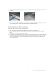
Chapter 5: Wireless Configuration This chapter describes how to configure the wireless features of your wireless router. In planning your wireless network, you should consider the level of security required. You should also select the appropriate placement of your Router in order to maximize the wireless performance. Guidelines to locate your Wireless Router The operating distance or range of your wireless connection can vary significantly based on the physical placement of the wireless router.
Enable Wireless. If you disable the wireless, wireless devices cannot connect to the wireless router. Mode. This field determines which data communication protocol will be used. You can keep the default setting “MIXED” if you have 802.11g and 802.11b devices in the network. “G_ONLY” dedicates the wireless router to communicating with the 802.11g wireless devices exclusively. “B_ONLY” dedicates the wireless router to communicating with the 802.11b wireless devices exclusively. ESSID.
modifications of this value are recommended. DTIM Interval. The default value is 1. This value, between 1 and 65,535 milliseconds, indicates the interval of the Delivery Traffic Indication Message (DTIM). A DTIM field is a countdown field informing clients of the next window for listening to broadcast and multicast messages. When the Router has buffered broadcast or multicast messages for associated clients, it sends the next DTIM with a DTIM Interval value.
There are two methods for creating WEP encryption keys: - Automatically. Enter a word or group of printable characters in the Passphrase box and click the Generate button. These characters are case sensitive. - Manually. There are two different key formats, Alphanumeric (also called ASCII) and Hexadecimal. For 64-bit WEP, enter 5 characters in Alphanumeric format, or 10 digits (any combination of 0-9, a-f, or A-F) in Hexadecimal format.
Configuring the basic wireless settings Follow the instructions below to set up and test basic wireless connectivity. Once you have established basic wireless connectivity, you can enable security settings appropriate to your needs. 1. Connect to the wireless router at its default IP address of http://192.168.62.1, or using whatever LAN IP address you have set up. 2. Click “Advanced Setup”, then key-in default user name of “admin” and default password of “1234”, or using whatever password you have set up.
Chapter 6: Advanced Configuration Advanced Setup The advanced setup menu is used to configure the LAN and WAN settings, as well as other advanced functions such as resetting the router, restoring to factory default settings, hosting services and upgrading to newer version of firmware, client filtering and special applications. For the instructions below to enter into the Advanced Setup: 1. Connect to the wireless router at its default IP address of http://192.168.62.
System - System Time Set the time zone for the Router and connecting to a Simple Network Time Protocol (SNTP) server which allows the Router to synchronize the system clock to the global Internet. The synchronized clock in the Router is used to record the security log and control client filtering. System - Administrator Settings Use this menu to restrict management access based on a specific password. The default password is 1234.
2. WAN IP address into the browser’s address of remote administrator, followed by a colon ‘:’ and the custom port number. For example, if Router’s WAN IP address is 210.61.49.227, you must enter http://210.61.49.227:8080 in the browser of remote administrator. To view the Router’s WAN IP address, you can check it from the Status screen. System - Firmware Update The Router software (firmware) of the wireless router is stored in flash memory, and can be upgraded as new firmware is released.
System - Status You can use the Status screen to see the connection status for the Router’s WAN/LAN interfaces. System - Security Log You may choose to Enable or Disable the Log feature. Click Apply to put your changes in effect, or click Cancel to undo your changes. 28 802.
Session Event Log Click Session Event Log to launch the Session Event Log Table window. In this screen, you can view session event entries. The Session Event Log Table shows Index number, Transport Type, Source IP, Source Port, Destination IP, Destination Port, and Terminate Reason. Click Refresh to see the latest data. Block Event Log Click Block Event Log to launch the Block Event Log Table window. In this screen, you can view blocking event entries.
WAN - PPPoE If your DSL provider says that you are connecting through PPPoE, perform these steps: a. Enter the User Name b. Enter the Password c. Reenter the password d. Enter the Service Name if your ISP requires it. This is optional. e. Keep the value of MTU as default setting. f. Note: MTU (Maximum Transmission Unit) is the largest frame size that can be transmitted over the network. Messages longer than the MTU must be divided into smaller frames. g.
WAN - PPTP Point to Point Tunneling Protocol (PPTP) is a service that applies to connections in Europe only. If your DSL provider says that you are connecting through PPTP, perform these steps: a. b. c. d. e. f. g. h. i. j. k. Enter the PPTP Account Enter the PPTP Password Reenter the PPTP Password Enter the Host Name if your ISP requires it. Enter Service IP Address. Your ISP will provide you with the Service IP Address. Enter My IP Address. This is the Router’s IP address, when seen from the Internet.
WAN - Static IP If you are required to use a permanent IP address to connect to the Internet, then select Static IP Address. a. Enter the IP address assigned by your ISP. This is the Router’s IP address, when seen from the Internet. Your ISP will provide you with the IP address you need to specify here. b. Enter Subnet Mask. This is the Router’s subnet mask, as seen by external users on the Internet. Your ISP will provide you with the subnet mask. c. Enter ISP Router Address.
WAN - DNS If your ISP will automatically assign DNS IP addresses to the Router, keep the default setting here, then click NEXT button. If your ISP does not automatically assign DNS IP addresses to the Router (e.g., when Static IP Address connection type is selected), enter the DNS IP address in the filed of Primary DNS address and Secondary DNS address. You need to enter at least primary DNS address.
WAN - Proxy DNS Use the Proxy DNS screen to map a domain name to its server’s IP address. This feature acts as a DNS server for the internal and DMZ networks, allowing you to connect to local machines without using an external DNS server. This simplifies network configuration and management. Setting Up Proxy DNS Servers In order to set up a computer on your network as a Proxy DNS Server, specify the Domain Name and Virtual IP Address.
LAN - LAN Settings The Router is shipped pre-configured to use private IP addresses on the LAN side, and to act as a DHCP server. The Router’s default LAN IP configuration is: LAN IP address: 192.168.62.1 Subnet Mask: 255.255.255.0 These addresses are part of IETF-designated private address range for use in private networks, and should be suitable in most applications. If your network has a requirement to use a different IP addressing scheme, you can make those changes in this screen.
LAN - DHCP Client List DHCP Client List allows the administrator to see which clients are connected to the Router via DHCP. NAT - Special Application Some applications require multiple connections, such as Internet gaming, video conferencing, Internet telephony and others. These applications cannot work when Network Address Translation (NAT) is enabled.
NAT - Virtual Server If you configure the Router as a virtual server, remote users who are accessing services such as Web or FTP at your local site via public IP addresses can be automatically redirected to local servers configured with private IP address. In other words, depending on the requested service (TCP/UDP port number), the Router redirects the external service requests to the appropriate servers. For example: If a local PC with a private IP address of 192.168.62.
Firewall - Client Filtering You can filter Internet access for local clients based on IP addresses For example, 192.168.62.60 ~ 192.168.62.65. Firewall – URL Filtering The feature allows you to restrict access based on web address. Up to 36 web addresses can be blocked in this feature. 38 802.
Firewall - DMZ (Demilitarized Zone) The DMZ hosting feature allows local PCs to be exposed to the Internet for use of a special-purpose service such as Internet gaming or videoconferencing. DMZ hosting forwards all the ports at the same time to the local PC. The Virtual Server or Special Application feature is more secure because it only opens the ports you want to have opened, while DMZ hosting opens all the ports of local computer, exposing the computer so the Internet can see it.
Appendix A: Troubleshooting This section describes common problems you may encounter during setup of the Router. If you cannot resolve any connection problems after checking the following solutions, please contact our tech support.
Appendix B: Specifications Standards: IEEE 802.3 10BASE-T, IEEE 802.3u 100 BASE-TX, IEEE 802.3x flow control IEEE 802.11b, IEEE 802.11g Wireless LAN Ports: LAN: Four 10/100Mbps RJ-45 Auto-MDI/MDIX switch ports WAN: One 10/100Mbps RJ-45 Auto-MDI/MDIX port for DSL/Cable modem Wireless Frequency band: 2.400 - 2.497 GHz Modulation Technique: DSSS (DBPSK, DQPSK, CCK), OFDM Data rate: 54 Mbps, 48, 36, 24, 18, 12, 11, 9, 6, 5.