
User's Guide
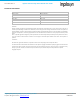
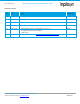
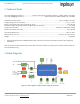
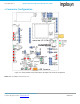
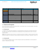
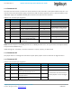
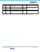
Table Of Contents
- 1. Introduction
- 2. Technical Data
- 3. Block Diagram
- 4. Connector Configuration
- 5. Test Points
- 6. LEDs
- 7. Schematic
- 8. Dimensions
- 9. Integration instructions for host product manufacturers according to KDB 996369 D03 OEM Manual v01
- 9.1. List of applicable FCC / ISED rules
- 9.2. Specific operational use conditions
- 9.3. Limited module procedures
- 9.4. Trace antenna designs
- 9.5. RF exposure considerations
- 9.6. Antennas
- 9.7. Label and compliance information
- 9.8. Information on test modes and additional testing requirements
- 9.9. Additional testing, Part 15 Subpart B disclaimer
- 9.10. Host Product Labelling Requirements
- 10. Disclaimer
- 11. References

NA-20-0386-0006-1.5 Inpixon Swarm Chirp V3 Dev Board User Guide
Inpixon_UG_Swarm_Chirp_V3_Dev_Board_1.5.docx 9
© Inpixon. All rights reserved. | www.inpixon.com FRM0008-A1
4.1.3. Connector X1
The Host Connector serves to connect the serial interface of a host controller to the Inpixon Swarm Chirp V3. It can
also be used as alternative power supply instead of the USB one. When supplied via pin 2 it takes precedence to the
USB power supply. The A_MODE and MOD_EN can also be controlled over this connector.
Table 4-2: X1 connector pin assignment
Pin No.
Description
Type
Module Pin
Comments
1
Ground
2
Vcc
Supply voltage
+3.1V…+5.5V
3
Ground
4
USART_RX
Input: Serial receiving line
19
If connected to a host remove
jumpers on X4. See Figure 4-2
5
USART_TX
Output: Serial transmission line
12
6
Not connected
7
Not connected
8
Not connected
9
A_MODE
Input: Autonomous (high) or
host-controlled mode (low)
9
Default high
10
MOD_EN
Input: Module enabled (high) or
disable (low)
11
Default high
Note: All levels except Vcc and MODE_EN refer to 2.6 V. MOD_EN refers to Vcc. In any case refer to the Inpixon Swarm
Chirp V3 Technical Reference [1].
USART settings are: 115.2 Kbps, 1 start bit, 8 data bits, 1 stop bit, no parity, no flow control
4.1.4. Connector X2
The Jumper Station is a storage area that serves to park spare jumpers. It has no electrical nor logical function.
4.1.5. Connector X3
Table 4-3: X3 connector pin assignment
Pin No.
Description
Type
Module Pin
Comments
1
Ground
2
ADC_IN
Input: Measures the voltage referred
to 2.6 V
21
2.6 V max.
3
DIO_0
Input or Output. Can be used for
wake-up and interrupt source
22
If connected to an external device
remove jumpers on X10. See Figure
4-3
4
DIO_1
Input or Output. Can be used as
interrupt source
23
5
DIO_2
Input or Output. Can be used as
interrupt source
24