
User's Guide
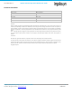
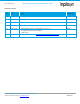
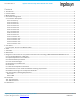
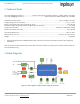
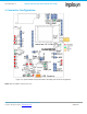
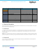
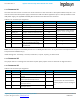
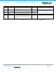
Table Of Contents
- 1. Introduction
- 2. Technical Data
- 3. Block Diagram
- 4. Connector Configuration
- 5. Test Points
- 6. LEDs
- 7. Schematic
- 8. Dimensions
- 9. Integration instructions for host product manufacturers according to KDB 996369 D03 OEM Manual v01
- 9.1. List of applicable FCC / ISED rules
- 9.2. Specific operational use conditions
- 9.3. Limited module procedures
- 9.4. Trace antenna designs
- 9.5. RF exposure considerations
- 9.6. Antennas
- 9.7. Label and compliance information
- 9.8. Information on test modes and additional testing requirements
- 9.9. Additional testing, Part 15 Subpart B disclaimer
- 9.10. Host Product Labelling Requirements
- 10. Disclaimer
- 11. References

NA-20-0386-0006-1.5 Inpixon Swarm Chirp V3 Dev Board User Guide
Inpixon_UG_Swarm_Chirp_V3_Dev_Board_1.5.docx 8
© Inpixon. All rights reserved. | www.inpixon.com FRM0008-A1
Table 4-1: Inpixon Swarm Chirp V3 Dev Board connector configuration
Connector No.
Description
Type
Default State
J1
RF port
SMA type, 50 Ohm impedance
Open
J2
USB
micro-USB
Open
X1
Host connector
Pin connector, 10 poles
Open
X2
Jumper station
Pin connector, 2 x 5 poles
Spare jumpers
X3
swarm bee LE pin header
Pin connector, 10 poles
Open
X4
USB to Serial bridge
Pin connector, 2 x 2 poles, jumper
Closed
X5
swarm bee LE pin header
Pin connector, 10 poles
Open
X6
Enable swarm bee LE module
Pin connector, 2 poles, jumper
Open
X7
Enable autonomous mode
Pin connector, 2 poles, jumper
Closed
X8
Pull-up or pull-down bridge
Pin connector, 3 poles, jumper
Open
X10
GPIO Jumper Matrix
Pin connector, 3 x 4 poles, jumper
Open
X11
Reserved
Connector, 10 poles
Reserved
X12
ADC input for measuring supply voltage
Pin connector, 2 poles, jumper
Closed
X13
Measurement of current profile
Pin connector, 2 poles, jumper
Closed
4.1. Connector Description
All electrical parameters except those explicitly stated in this document refer to the ones specified in the Inpixon
Swarm Chirp V3 Technical Reference [1].
4.1.1. Connector J1
J1 is a SMA connector with 50 Ohm impedance. It is terminated directly to the RF port of the Inpixon Swarm Chirp
V3 module. The output power is calibrated that the radiated power at the provided antenna is close to but never
exceeds +20 dBm.
Note: When using another antenna and to be in accordance with CE, FCC and ISED it is required to adapt the emitted
power by the gain of the antenna by using the STXP API command. The procedure is explained in section 9.8.
4.1.2. Connector J2
J2 is a standard micro-USB-B connector to connect the Inpixon Swarm Chirp V3 Dev Board to a host PC (data and
power) or a USB power pack or supply.