
User's Guide
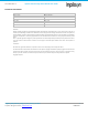
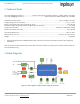
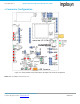
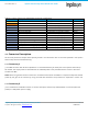
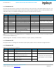
Table Of Contents
- 1. Introduction
- 2. Technical Data
- 3. Block Diagram
- 4. Connector Configuration
- 5. Test Points
- 6. LEDs
- 7. Schematic
- 8. Dimensions
- 9. Integration instructions for host product manufacturers according to KDB 996369 D03 OEM Manual v01
- 9.1. List of applicable FCC / ISED rules
- 9.2. Specific operational use conditions
- 9.3. Limited module procedures
- 9.4. Trace antenna designs
- 9.5. RF exposure considerations
- 9.6. Antennas
- 9.7. Label and compliance information
- 9.8. Information on test modes and additional testing requirements
- 9.9. Additional testing, Part 15 Subpart B disclaimer
- 9.10. Host Product Labelling Requirements
- 10. Disclaimer
- 11. References

NA-20-0386-0006-1.5 Inpixon Swarm Chirp V3 Dev Board User Guide
Inpixon_UG_Swarm_Chirp_V3_Dev_Board_1.5.docx 6
© Inpixon. All rights reserved. | www.inpixon.com FRM0008-A1
2. Technical Data
User and debugging interface 1 ......................... Inpixon Swarm Chirp V3 USART, 500 bps to 1 Mbps, default 115.2kbps
User and debugging interface 2 ............................................................. USB, converted to USART by FTDI chip, 115.2kbps
Radiated TX output power ................................................................................................................ max. +20 dBm / 100 mW
1
Supply voltage via host connector ........................................................................................................................ +3.1 V…+5.5 V
Power consumption over host connector (@ 3.3 V) ............................................................................................ max. 250 mA
Maximum supply voltage ripple when supplied via host connector ....................................................................... 30 mVpp
Supply via micro-USB .............................................................................................................. standard 5 V USB power supply
Power consumption over USB ............................................................................................................................... max. 200 mA
Operating temperature .........................................................................................................................................-30°C to +85°C
Dimensions (L x W x H) .................................................................................................................... 80 mm x 100 mm x 22 mm
Weight ............................................................................................................................................................................... 46 grams
1. Only with supplied antenna PSKN3-24/55S. Other antennas connected to the SMA connector will infringe any
certification
Note: All technical data related to the Inpixon Swarm Chirp V3 module can be found in the Inpixon Swarm Chirp V3
Technical Reference [1]
3. Block Diagram
Figure 3-1: Block diagram of Inpixon Swarm Chirp V3 Dev Board