
User's Guide
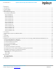
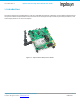
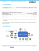
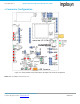
Table Of Contents
- 1. Introduction
- 2. Technical Data
- 3. Block Diagram
- 4. Connector Configuration
- 5. Test Points
- 6. LEDs
- 7. Schematic
- 8. Dimensions
- 9. Integration instructions for host product manufacturers according to KDB 996369 D03 OEM Manual v01
- 9.1. List of applicable FCC / ISED rules
- 9.2. Specific operational use conditions
- 9.3. Limited module procedures
- 9.4. Trace antenna designs
- 9.5. RF exposure considerations
- 9.6. Antennas
- 9.7. Label and compliance information
- 9.8. Information on test modes and additional testing requirements
- 9.9. Additional testing, Part 15 Subpart B disclaimer
- 9.10. Host Product Labelling Requirements
- 10. Disclaimer
- 11. References

NA-20-0386-0006-1.5 Inpixon Swarm Chirp V3 Dev Board User Guide
Inpixon_UG_Swarm_Chirp_V3_Dev_Board_1.5.docx 5
© Inpixon. All rights reserved. | www.inpixon.com FRM0008-A1
1. Introduction
The Inpixon Swarm Chirp V3 Dev Board is a CE, FCC and ISED certified tool to develop, test and debug software based
on Inpixon's Swarm Chirp V3 module. Several connectors and test points help to measure particular parameters, such
as RF output power or current consumption.
Figure 1-1: Inpixon Swarm Chirp V3 Dev Board