
User's Guide
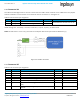

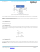
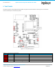
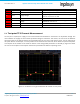
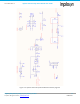
Table Of Contents
- 1. Introduction
- 2. Technical Data
- 3. Block Diagram
- 4. Connector Configuration
- 5. Test Points
- 6. LEDs
- 7. Schematic
- 8. Dimensions
- 9. Integration instructions for host product manufacturers according to KDB 996369 D03 OEM Manual v01
- 9.1. List of applicable FCC / ISED rules
- 9.2. Specific operational use conditions
- 9.3. Limited module procedures
- 9.4. Trace antenna designs
- 9.5. RF exposure considerations
- 9.6. Antennas
- 9.7. Label and compliance information
- 9.8. Information on test modes and additional testing requirements
- 9.9. Additional testing, Part 15 Subpart B disclaimer
- 9.10. Host Product Labelling Requirements
- 10. Disclaimer
- 11. References

NA-20-0386-0006-1.5 Inpixon Swarm Chirp V3 Dev Board User Guide
Inpixon_UG_Swarm_Chirp_V3_Dev_Board_1.5.docx 16
© Inpixon. All rights reserved. | www.inpixon.com FRM0008-A1
TP No.
Description
Function
Comments
TP6
/TX_RX
Hardware TX indicator
TX = low, RX (2.65 V) = high (nanoLOC)
TP7
GND
Ground
TP8
VCC*
Supply voltage
Supply voltage of the swarm bee LE module applied
either on X1 pin2 or on USB
TP9
GND
Ground
TP10
ICC/U
Supply current converted to
voltage
Supply current is converted to a voltage, ratio is 1:10
(100mA/1V), see sect. 5.1
TP11
ICC
Current measurement
Same function as X13, see chap. 4.1.14
TP12
ICC
Current measurement
Same function as X13, see chap. 4.1.14
5.1. Test point TP10 Current Measurement
On test point 10 (TP10) the supply current of the swarm bee LE module is converted to an equivalent voltage. The
ratio between the supply current and the equivalent voltage is 100mA/1V. This means, the current of the different
operating states of the Inpixon Swarm Chirp V3 module like the TX current and the RX current, can be measured at
this point. With an oscilloscope, a current profile can be measured over the time, which allows to optimize the power
consumption of the module to the needs in relation to the configurable parameters via the API [2]. Figure 5-2 shows
the current consumption of the Inpixon Swarm Chirp V3 module at different operating states.
Figure 5-2: Screenshot of a typical swarm bee LE module current profile