
User's Guide

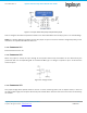
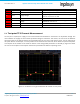
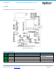
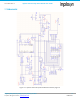
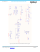
Table Of Contents
- 1. Introduction
- 2. Technical Data
- 3. Block Diagram
- 4. Connector Configuration
- 5. Test Points
- 6. LEDs
- 7. Schematic
- 8. Dimensions
- 9. Integration instructions for host product manufacturers according to KDB 996369 D03 OEM Manual v01
- 9.1. List of applicable FCC / ISED rules
- 9.2. Specific operational use conditions
- 9.3. Limited module procedures
- 9.4. Trace antenna designs
- 9.5. RF exposure considerations
- 9.6. Antennas
- 9.7. Label and compliance information
- 9.8. Information on test modes and additional testing requirements
- 9.9. Additional testing, Part 15 Subpart B disclaimer
- 9.10. Host Product Labelling Requirements
- 10. Disclaimer
- 11. References

NA-20-0386-0006-1.5 Inpixon Swarm Chirp V3 Dev Board User Guide
Inpixon_UG_Swarm_Chirp_V3_Dev_Board_1.5.docx 12
© Inpixon. All rights reserved. | www.inpixon.com FRM0008-A1
Pin No.
Description
Type
Module Pin
Comments
9
Reserved
-
Do not use
10
Reserved
-
Do not use
Note: All levels refer to 2.6 V. In any case refer to the Inpixon Swarm Chirp V3 Technical Reference [1].
4.1.8. Connector X6
Is a jumper bridge which enables or disables the Inpixon Swarm Chirp V3 module.
Table 4-6: X6 connector pin assignment
Pin No.
Description
Type
Module Pin
Comments
1-2
MOD_EN
Jumper
11
Closed: disabled, Open: enabled
Note: MOD_EN level refers to Vcc. In any case refer to the Inpixon Swarm Chirp V3 Technical Reference [1].
4.1.9. Connector X7
Is a jumper bridge which sets the Inpixon Swarm Chirp V3 module into autonomous or host-controlled mode.
Table 4-7: X7 connector pin assignment
Pin No.
Description
Type
Module Pin
Comments
1-2
A_MODE
Jumper
9
Closed: host controlled
Open: autonomous mode
Note: All levels refer to 2.6 V. In any case refer to the Inpixon Swarm Chirp V3 Technical Reference [1].
4.1.10. Connector X8
The pull-up or pull-down bridge serves in conjunction with jumper matrix X10 to determine the logical level of the
GPIOs if configured as input. See Figure 4-3.
Table 4-8: X8 connector pin assignment
Pin No.
Description
Type
Module Pin
Comments
1-2
Pull-up
+2.6V
13
Logic high
2-3
Pull-down
Ground
Logic low
4.1.11. Connector X10
This jumper matrix can be used to either set a GPIO pin to logical high or low if configured as input or to display the
state of a GPIO through a LED when configured as output. Figure 4-3 shows the principle. The RC element 1K/47µF
composes an elementary debouncing circuit.