
User's Guide
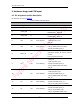
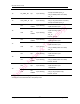
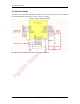
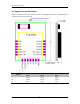
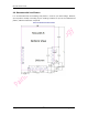
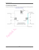
Table Of Contents

Mouselet-B User Guide
All rights reserved Suzhou Pairlink Network Technology Co.,Ltd.
- 5 -
4. Hardware design and PCB layout
4.1. Pin assignment and Pin description
Pin definition can refer to Figure 2.
Table 1:Module Pin Description
Pin Number
Pin Name
I/O
After POR status
Alternate Function Description
7
VPP_3V3
I
-
Power Supply
1, 4, 13
GND
-
Connect to Ground
5
UART_RXD
I
-
UART serial input
DEBUG PORT:UART-RX
6
UART-TXD
O
-
UART serial output
DEBUG PORT:UART-TX
2
P15
I/O
Input floating
• GPIO: P15
• A/D converter input
• IR_RX
3
P25
I/O
Input floating
• GPIO: P25
• SPI_2: MISO (master and slave)
• Peripheral UART: puart_rx
8
RESET_N
I/O
-
Active-low system reset with
open-drain output & internal pull-up
resistor
Do not connect if unused
9
P0
(a)
I/O
Input floating
• GPIO: P0
• A/D converter input
• Peripheral UART: puart_tx
• SPI_2: MOSI (master and slave)
• IR_RX
10
P1
I/O
Input floating
• GPIO: P1
• A/D converter input
• Peripheral UART: puart_rts
• SPI_2: MISO (master and slave)
• IR_TX
11
P3
I/O
Input floating
• GPIO: P3
• Peripheral UART: puart_cts
• SPI_2: SPI_CLK (master and slave)
12
P2
I/O
Input floating
• GPIO: P2
• Peripheral UART: puart_rx
• SPI_2: SPI_CS (slave only)
• SPI_2: SPI_MOSI (master only)