
Operation Manual
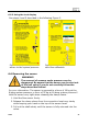
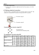
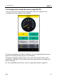
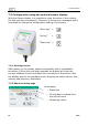
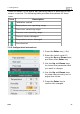
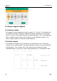
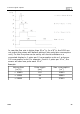
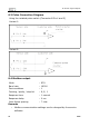
Table Of Contents
- 1. Safety instructions
- 2. Application
- 3. Features
- 4. Technical Data
- 5. Dimensional drawing
- 6. Installation
- 7. Configuration
- 8. Sensor signal outputs
- 9. Calibration
- 10. Maintenance
- 11. Disposal or waste
- 12. Warranty
- Appendix

6.5.3 Using the local display
See steps 4 and 5 described in the following Figure 3.
Figure 2: Steps to expose the
sensor to the system pressure
Figure 3: Steps to perform the
zero flow calibration
6.6 Removing the sensor
WARNING!
The removal of sensors under pressure can be
dangerous! Be aware that the sensor can be shot out
of the ball valve if you do not carefully follow the
steps described below!
For your information: The sensor is exposed to a force of 18 kg at the
8-barg system pressure; a force of 32 kg at 16-barg system pressure!!
Hold the sensor very tight when releasing the clamp sleeve.
1. Hold the flow sensor firmly.
2. Release the clamp sleeve from the connection head very slowly
while keeping your hand on the top of the sensor head.
3. Pull out the shaft slowly until the sensor is fully returned into the
value.
S430 21