
Operation Manual
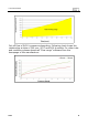
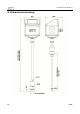
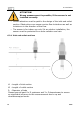
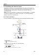
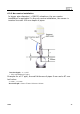
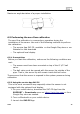
Table Of Contents
- 1. Safety instructions
- 2. Application
- 3. Features
- 4. Technical Data
- 5. Dimensional drawing
- 6. Installation
- 7. Configuration
- 8. Sensor signal outputs
- 9. Calibration
- 10. Maintenance
- 11. Disposal or waste
- 12. Warranty
- Appendix

6. Installation
ATTENTION!
Wrong measurement is possible, if the sensor is not
installed correctly.
• Careful attention must be paid to the design of the inlet and outlet
section. Obstructions can cause counter-flow turbulence as well as
turbulence in the direction of the flow.
• The sensor is for indoor use only! At an outdoor installation, the
sensor must be protected from solar radiation and rain.
6.2.1 Inlet and outlet sections
L1 : Length of inlet section
L2 : Length of outlet section
D : Diameter of tube
Please keep at least 8 x D upstream and 3 x D downstream to ensure
an significant influence to the measuerement due to up and
downstreampipe bends.
14 S430