
Operation Manual

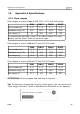
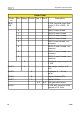
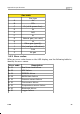
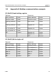
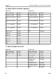
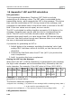
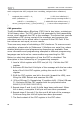

Table Of Contents
- 1 Safety instructions
- 2 RF Exposure Information and Statement
- 3 Application
- 4 Features
- 5 Technical Data
- 6 Dimensional drawing
- 7 Installation
- 8 Sensor signal outputs
- 9 Configuration
- 10 Data logging
- 11 Calibration
- 12 Disposal or waste
- 13 12 Warranty
- 14 Appendix A Specifications
- 15 Appendix B Modbus communication example
- 16 Appendix C LRC and CRC calculation

Appendix A Specifications
Order Table
Order
no.
Size Range Output Gas 1 Gas 2 Description
S695
418
S 418, thermal mass flow
meter, 1.5% o.RDG., 24
VDC
0 DN8 G inner thread
1 DN15 G inner thread
2 DN20 G inner thread
3 DN25 G inner thread
5 DN8 G inner thread, inc.
pressure
6 DN15 G inner thread, inc.
pressure
7 DN20 G inner thread, inc.
pressure
8 DN25 G inner thread, inc.
pressure
S Standard range version of
S 418
A1453 L Low range version of S
418
A1455 A Analogue 4 … 20 mA,
pulse
A1456 B Digital Modbus/RTU
A1457 C Digital M-Bus
A-Z B-Z See gas table below
A1459 S 418 with imperial units
instead of SI units
24 S 418