
Operation Manual
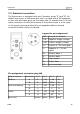


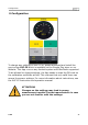


Table Of Contents
- 1 Safety instructions
- 2 RF Exposure Information and Statement
- 3 Application
- 4 Features
- 5 Technical Data
- 6 Dimensional drawing
- 7 Installation
- 8 Sensor signal outputs
- 9 Configuration
- 10 Data logging
- 11 Calibration
- 12 Disposal or waste
- 13 12 Warranty
- 14 Appendix A Specifications
- 15 Appendix B Modbus communication example
- 16 Appendix C LRC and CRC calculation

Installation
ATTENTION!
Do not screw the M8 plug using force. Otherwise, it may
damage the connecting pins.
8 Sensor signal outputs
8.1 Analog output
The sensor has an analog output range of 4 ... 20 mA. This output can
be scaled to match a desired measuring range. Standard scaling is from
0 to the max flow. The corresponding flow in different pipe sizes can be
found in Appendix A.
8.2 Pulse output
The sensor will send out one pulse per consumption unit. This pulse
output can be connected to an external pulse counter to count the total
consumption. The number of m
3
per second are summed up and
indicated after one second. Pulse length depends on flow rate.
14 S 418