
Operation Manual
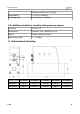
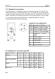


Table Of Contents
- 1 Safety instructions
- 2 RF Exposure Information and Statement
- 3 Application
- 4 Features
- 5 Technical Data
- 6 Dimensional drawing
- 7 Installation
- 8 Sensor signal outputs
- 9 Configuration
- 10 Data logging
- 11 Calibration
- 12 Disposal or waste
- 13 12 Warranty
- 14 Appendix A Specifications
- 15 Appendix B Modbus communication example
- 16 Appendix C LRC and CRC calculation

Installation
7.2 Electrical connection
The flow sensor is equipped with two Connector plugs “A” and “B”. By
default the sensor is delivered with one 5 m cable with a M8 connector
on one side and open wires on the other side. To operate the S 418 one
cable connection is sufficient however if the pulse output is to be used
or the supply and signal should be on separate cables a second
connection cable has to be ordered.
Legend to pin assignment
GND: Ground for Modbus
-VB: Negative supply voltage
+VB: Positive supply voltage
I+: Positive 4...20 mA signal
I-: Negative 4... 20 mA
signal
D+: Modbus data +
D-: Modbus data -
P: Pulse signal
M: M-Bus data
NC: Not connected
Pin assignment connector plug M8
Output Version Connector Pin 1 Pin 2 Pin 3 Pin 4
Modbus A D- -VB +VB D+
B D- GND GND D+
Pulse and analog A I- -VB +VB I+
B I- P P I+
M-Bus A M -VB +VB M
B M NC NC M
Wire color brown white blue black
S 418 13