
Operation Manual

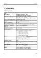
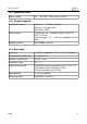
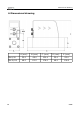
Table Of Contents
- 1 Safety instructions
- 2 RF Exposure Information and Statement
- 3 Application
- 4 Features
- 5 Technical data
- 6 Dimensional drawing
- 7 Installation
- 8 Sensor signal outputs
- 9 Configuration
- 10 Calibration
- 11 Disposal or waste
- 12 Warranty
- 13 Appendix A – Specifications
- 14 Appendix B - Modbus communication example
- 15 Appendix C - LRC and CRC calculation

Technical data
5.2 Electrical data
Power supply 15 ... 30 VDC, 120 mA @ 24 VDC
5.3 Output-signals
Analogue output Signal: 4 ... 20 mA, isolated
Scaling: 0 to max flow
Max load: 250R
Pulse output 1 pulse per m
3
, isolated switch, max. 30
VDC, 200 mA
(pulse length: 10 ... 120 ms, depends on flow
rate)
Modbus output See Modbus output.
5.4 Accuracy
Accuracy ± 3.0% of reading ± 0.3% F.S. (Full Scale)
Temperature coefficient < 0.1%/K F.S.
Pressure coefficient <0.5% / bar
Turndown ratio 50 : 1
Stated accuracy at Ambient/process temperature 23 °C ± 3 °C
Ambient/process humidity <90%
Process pressure at 0.6 MPa
Repeatability ± 1% of reading
Sampling rate 3 samples / second
S 415 9