
Operation Manual

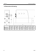
Table Of Contents
- 1 Safety instructions
- 2 RF Exposure Information and Statement
- 3 Application
- 4 Features
- 5 Technical data
- 6 Dimensional drawing
- 7 Installation
- 8 Sensor signal outputs
- 9 Configuration
- 10 Calibration
- 11 Disposal or waste
- 12 Warranty
- 13 Appendix A – Specifications
- 14 Appendix B - Modbus communication example
- 15 Appendix C - LRC and CRC calculation

Features
5 Technical data
5.1 General
FCC ID: 2ASK2-SUTO-002
Parameters Standard unit flow: l/min
Consumption units: m³ (default)
Reference conditions ISO1217 20 °C 1000 mbar (Standard-Unit)
DIN1343 0 °C 1013.25 mbar (Norm-Unit)
Principle of measurement Thermal mass flow
Sensor Glass coated resistive sensor
Measuring medium Air, N
2
Operating temperature 0 ... 50 °C fluid temperature and casing
Humidity of the meas.
medium
< 90%, no condensation
Operating pressure 0 ... 1.0 MPa
Pressure drop Maximum pressure drop at the maximum
flow of standard calibration range:
• DN8 type : 30 hPa
• DN15 type: 100 hPa
• DN20 type: 100 hPa
• DN25 type: 200 hPa
Casing Process connection: aluminum alloy
Wetted parts: aluminum alloy
Top casing: PC + ABS
Protection class IP54
Dimensions See dimensional drawing on the next page
Display 4-digit LED display
Tube diameter DN8, DN15, DN20, DN25
Process connection G inner thread ISO 228-1
Weight 0.45 kg (DN8), 0.44 kg (DN15)
0.97 kg (DN20), 0.94 kg (DN25)
8 S 415