
Operation Manual
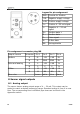

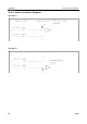


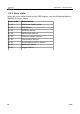
Table Of Contents
- 1 Safety instructions
- 2 RF Exposure Information and Statement
- 3 Application
- 4 Features
- 5 Technical data
- 6 Dimensional drawing
- 7 Installation
- 8 Sensor signal outputs
- 9 Configuration
- 10 Calibration
- 11 Disposal or waste
- 12 Warranty
- 13 Appendix A – Specifications
- 14 Appendix B - Modbus communication example
- 15 Appendix C - LRC and CRC calculation

Sensor signal outputs
8.3 Modbus output
Mode : RTU
Baud rate : 19200
Device address : 1
Framing / parity / stop bit : 8, N, 1
Response timeout : 1 second
Response delay : 0 ms
Inter-frame spacing : 7 char
Remark
• Modbus communication settings can be changed by the service app
S4C-FS
• To learn more about Modbus communication, see Appendix B -
Modbus communication example and Appendix C - LRC and CRC
calculation.
Index Channel description Resolution Format Length
Modbus
address
1 Flow 0.1 FLOAT 4 Byte 6
2 Consumption 1 UNIT32 4 Byte 8
Remarks
• All numbers are in little-endian format.
• Function code: 03.
• The measurement value is always available in the programmed
physical unit.
S 415 15