
Operation Manual
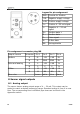

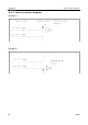


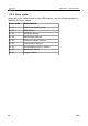
Table Of Contents
- 1 Safety instructions
- 2 RF Exposure Information and Statement
- 3 Application
- 4 Features
- 5 Technical data
- 6 Dimensional drawing
- 7 Installation
- 8 Sensor signal outputs
- 9 Configuration
- 10 Calibration
- 11 Disposal or waste
- 12 Warranty
- 13 Appendix A – Specifications
- 14 Appendix B - Modbus communication example
- 15 Appendix C - LRC and CRC calculation

Installation
Legend to pin assignment
GND: Ground for Modbus
-VB: Negative supply voltage
+VB: Positive supply voltage
I+: Positive 4...20 mA signal
I-: Negative 4... 20 mA
signal
D+: Modbus data +
D-: Modbus data -
P: Pulse signal
M: M-Bus data
NA: Not applicable
Pin assignment connector plug M8
Output Version Connector Pin 1 Pin 2 Pin 3 Pin 4
Modbus A D- -VB +VB D+
B D- GND GND D+
Pulse and analog A I- -VB +VB I+
B I- P P I+
M-Bus A M -VB +VB M
B M NA NA M
Wire color brown white blue black
8 Sensor signal outputs
8.1 Analog output
The sensor has an analog output range of 4 ... 20 mA. This output can be
scaled to match a desired measuring range. Standard scaling is from 0 to max
flow. The corresponding flow in different pipe sizes can be found in the
Appendix section.
12 S 415