English Instruction and operation manual S 415 Thermal mass flow sensor FCC ID:2ASK2-SUTO-002
Dear Customer, Thank you for choosing our product. Please read the operating instructions in full and carefully observe them before you start up the device. The manufacturer cannot be held liable for any damage which occurs as a result of non-observance or noncompliance with this manual. Should the device be tampered with in any manner other than a procedure which is described and specified in the manual, the warranty is canceled and the manufacturer is exempt from liability.
内容目录 1 2 3 4 5 Safety instructions......................................................................4 RF Exposure Information and Statement........................................6 Application.................................................................................7 Features....................................................................................7 Technical data.............................................................................8 5.1 General..................................
Safety instructions 1 Safety instructions Please check if this instruction manual accords to the product type. Please observe all notes and instructions indicated in this manual. It contains essential information which must be observed before and during installation, operation and maintenance. Therefore this instruction manual must be read carefully by the technician as well as by the responsible user / qualified personnel.
Safety instructions WARNING! Permitted operating parameters! Observe the permitted operating parameters, any operation exceeding this parameters can lead to malfunctions and may lead to damage on the instrument or the system. • Do not exceed the permitted operating parameters. • Make sure the product is operated in its permitted limitations. • Do not exceed or undercut the permitted storage and operation temperature and pressure.
Safety instructions • For storage and transportation it is recommended to use the packaging which comes with the sensor. • Please make sure that storage temperature of the sensor is between -10 °C ... 50 °C. • Avoid direct UV and solar radiation during storage. • For the storage the humidity has to be <90%, no condensation. 2 RF Exposure Information and Statement This equipment complies with FCC RF radiation exposure limits set forth for an uncontrolled environment.
RF Exposure Information and Statement - Reorient or relocate the receiving antenna. - Increase the separation between the equipment and receiver. -Connect the equipment into an outlet on a circuit different from that to which the receiver is connected. -Consult the dealer or an experienced radio/TV technician for help -This device and its antenna(s) must not be co-located or operating in conjunction with any other antenna or transmitter.
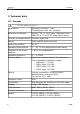
Features 5 Technical data 5.1 General FCC ID: 2ASK2-SUTO-002 Parameters Standard unit flow: l/min Consumption units: m³ (default) Reference conditions ISO1217 20 °C 1000 mbar (Standard-Unit) DIN1343 0 °C 1013.25 mbar (Norm-Unit) Principle of measurement Thermal mass flow Sensor Glass coated resistive sensor Measuring medium Air, N2 Operating temperature 0 ... 50 °C fluid temperature and casing Humidity of the meas. medium < 90%, no condensation Operating pressure 0 ... 1.
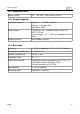
Technical data 5.2 Electrical data Power supply 15 ... 30 VDC, 120 mA @ 24 VDC 5.3 Output-signals Analogue output Signal: 4 ... 20 mA, isolated Scaling: 0 to max flow Max load: 250R Pulse output 1 pulse per m3 , isolated switch, max. 30 VDC, 200 mA (pulse length: 10 ... 120 ms, depends on flow rate) Modbus output See Modbus output. 5.4 Accuracy Accuracy ± 3.0% of reading ± 0.3% F.S. (Full Scale) Temperature coefficient < 0.1%/K F.S. Pressure coefficient <0.
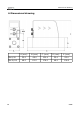
Dimensional drawing 6 Dimensional drawing A (mm) B (mm) C (mm) D (mm) E (mm) DN 8/15 35.0 48.0 120.4 35.0 93.0 DN 20/25 48.0 61.0 178.0 48.0 106.
Installation 7 Installation S 415 is delivered with following components: Qty. Description Item no. 1 S 415 Thermal mass flow meter S695 S695 S695 S695 1 5 m cable with M8 connector and open ends A553 0136 1 Instruction manual No P/N 1 Calibration certificate No P/N 4150 4151 4152 4153 7.1 Installation considerations In order to maintain the accuracy stated in the technical data, the sensor must be installed inline and fitted to tubes with the same diameter.
Installation Legend to pin assignment GND: Ground for Modbus -VB: Negative supply voltage +VB: Positive supply voltage I+: Positive 4...20 mA signal I-: Negative 4...
Sensor signal outputs 8.2 Pulse output The sensor will send out one pulse per consumption unit. This pulse output can be connected to an external pulse counter to count the total consumption. The number of m3 per second are summed up and indicated after one second. Pulse length depends on flow rate. Volumetric flow [m3/s] Volumetric flow [m3/h] Pulse length [ms] Max.
Sensor signal outputs 8.2.
Sensor signal outputs 8.3 Modbus output Mode : RTU Baud rate : 19200 Device address :1 Framing / parity / stop bit : 8, N, 1 Response timeout : 1 second Response delay : 0 ms Inter-frame spacing : 7 char Remark • Modbus communication settings can be changed by the service app S4C-FS • To learn more about Modbus communication, see Appendix B Modbus communication example and Appendix C - LRC and CRC calculation. Index Channel description Resolution Format Length Modbus address 1 Flow 0.
Configuration 9 Configuration Please download the service app from the Google Play Store in case you need to have any settings changed on the S 415. The app is running on any Android system with Bluetooth supported. To change settings the app needs to scan the QR code on the calibration certificate at first. This ensures that only valid users can access the sensor settings. Follow the instructions in the service app.
Calibration 10 Calibration The sensor is calibrated ex work. The exact calibration date is printed on the certificate which is supplied together with the sensor. The accuracy of the sensor is regulated by the on site conditions, parameters like oil, high humidity or other impurities can affect the calibration and furthermore the accuracy. However we recommend to calibrate the instrument at least once per year. The calibration is excluded from the instruments warranty.
Warranty The warranty is canceled: • If the user opens the measurement instrument without a direct request written in this instruction manual. • If repairs or modifications are undertaken by third parties or unauthorized persons. • If the serial number has been changed, damaged or removed. Other claims, especially those for damage occurring outside the instrument are not included unless responsibility is legally binding. Warranty repairs do not extend the period of warranty.
Appendix A – Specifications 13 Appendix A – Specifications 13.1 Flow ranges Flow ranges in sl/min of air at ISO 1217: 20°C and 1000 mbar: DN8 DN15 DN20 DN25 0 1 2 3 250 1000 2000 3500 50 200 400 700 Size Standard range (S) Low range (L) Flow ranges in sl/min of N2 at 0°C and 1013.25 mbar: DN8 DN15 DN20 DN25 0 1 2 3 Standard range (S) 222 890 1780 3110 Low range (L) 44.5 178 356 622 Size Order Table (Air and N2 only) Order no.
Appendix A – Specifications 13.2 Error code When an error code shows on the LED display, use the following table to identify the error cause. Error code Description Er. 01 Real time clock failure Er. 02 ADC failure Er. 04 EEPROM failure Er. 08 NADN flash failure Er. 10 Pressure sensor failure Er. 20 Flow sensor failure Er. 30 Temperature sensor failure Er. 40 Bluetooth failure Er.
Appendix B - Modbus communication example 14 Appendix B - Modbus communication example 03 (0x03) Read holding register Request Response Slave address 1 byte Slave address 1 byte Function code 1 byte Function code 1 byte Starting address 1 byte Hi Byte count 1 byte Starting address 1 byte Lo Register Hi 1 byte No. of points Hi 1 byte Register Lo 1 byte No.
Appendix B - Modbus communication example 16 (0x10) Write multiple registers Request Response Slave address 1 byte Slave address 1 byte Function code 1 byte Function code 1 byte Starting address 1 byte Hi Starting address 1 byte Hi Starting address 1 byte Lo Starting address 1 byte Lo No. of registers Hi 1 byte No. of registers Hi 1 byte No. of registers Lo 1 byte No.
Appendix C - LRC and CRC calculation 15 Appendix C - LRC and CRC calculation LRC generation The Longitudinal Redundancy Checking (LRC) field is one byte, containing an 8–bit binary value. The LRC value is calculated by the transmitting device, which appends the LRC to the message. The device that receives recalculates an LRC during receipt of the message, and compares the calculated value to the actual value it received in the LRC field. If the two values are not equal, an error results.
Appendix C - LRC and CRC calculation LRC generation function static unsigned char LRC(unsigned char *auchMsg, unsigned short usDataLen) { unsigned char uchLRC = 0 ; while (usDataLen––) uchLRC += *auchMsg++ ; /* LRC char initialized */ /* pass through message buffer */ /* add buffer byte without carry */ return ((unsigned char)(–((char)uchLRC))) ; /* return twos complement */ } CRC generation The Cyclical Redundancy Checking (CRC) field is two bytes, containing a 16-bit binary value.
Appendix C - LRC and CRC calculation 8. When the CRC is placed into the message, its upper and lower bytes must be swapped as described below. Placing the CRC into the message When the 16-bit CRC (two 8-bit bytes) is transmitted in the message, the low-order byte will be transmitted first, followed by the high-order byte.
Appendix C - LRC and CRC calculation 0xFB, 0x39, 0xF9, 0xF8, 0x38, 0x28, 0xE8, 0xE9, 0x29, 0xEB, 0x2B, 0x2A, 0xEA, 0xEE, 0x2E, 0x2F, 0xEF, 0x2D, 0xED, 0xEC, 0x2C, 0xE4, 0x24, 0x25, 0xE5, 0x27, 0xE7, 0xE6, 0x26, 0x22, 0xE2, 0xE3, 0x23, 0xE1, 0x21, 0x20, 0xE0, 0xA0, 0x60, 0x61, 0xA1, 0x63, 0xA3, 0xA2, 0x62, 0x66, 0xA6, 0xA7, 0x67, 0xA5, 0x65, 0x64, 0xA4, 0x6C, 0xAC, 0xAD, 0x6D, 0xAF, 0x6F, 0x6E, 0xAE, 0xAA, 0x6A, 0x6B, 0xAB, 0x69, 0xA9, 0xA8, 0x68, 0x78, 0xB8, 0xB9, 0x79, 0xBB, 0x7B, 0x7A, 0xBA, 0xBE, 0x7E,
S 415 27
SUTO iTEC GmbH SUTO iTEC (ASIA) Co., Ltd. Tel: +49 (0) 7631 936889-0 Fax: +49 (0) 7631 936889-19 Email: sales@suto-itec.com Website: http://www.suto-itec.com Tel: +852 2328 9782 Fax: +852 2671 3863 Email: sales@suto-itec.asia Website: http://www.suto-itec.com Werkstr. 2 79426 Buggingen Germany All rights reserved © 28 Room 10, 6/F, Block B, Cambridge Plaza 188 San Wan Road, Sheung Shui, N.T. Hong Kong Modifications and errors reserved.