USER MANUAL SurgeX XR315 SurgeX® Surge Eliminator Software Version 1.0 1 DESCRIPTION ..................................................................................................................................... 3 2 FEATURES ........................................................................................................................................... 4 3 INSTALLATION ...................................................................................................................
3.1 120 VOLT CONNECTIONS ................................................................................................................... 5 3.2 REMOTE CONTROL CONNECTIONS ................................................................................................... 5 3.2.1 UP/DOWN CONTROL INPUTS ............................................................................................................. 5 3.2.2 OVER-RIDE INPUT .........................................................................
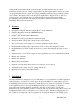
1 Description The SurgeX® XR315 is a 120V, 15 Amp AC power quality product incorporating SurgeX® Advanced Series Mode® power conditioning and surge protection. The surge protection is rated A-1-1, the highest standard of the Federal Commercial Item Description for Endurance. The one rack-space steel enclosure is designed to be installed in a 19 inch equipment rack, or placed on a flat surface. A total of eight 120V receptacles are provided on the rear panel.
A plug-in Phoenix terminal block on the rear panel accommodates the remote control connections and also the low-voltage outputs. There are three inputs which control power state; one programmable 12V DC output; and one programmable auxiliary relay providing normallyopen contacts. The inputs can be controlled by an applied DC voltage from 5V to 30V, by a contact closure, or by different types of switch; the input selection being made during programming.
tap. *CAUTION: Do not install this device if there is not at least 10 meters (30 feet) or more between the electrical outlet and the electrical service panel. 3.1 120 Volt Connections The XR315 has a total of 8 receptacles. Each receptacle is rated for a maximum load of 15 amps but the total load of the XR315 must not exceed 15 amps. 3.2 Remote Control Connections Remote connections are wired to the green 7-pin plug-in Phoenix terminal block on the rear of the unit next to the power cord.
b) Contact Closure: The XR315 will power up when the contacts are closed and power down when the contacts are open. Connect the two wires from the contacts to “up” and “common”. Program the input for “Latching” c) Momentary Switch(es): The XR315 will power up when a switch is pressed once and power down when a switch is pressed a second time. Connect the two wires from the switch(es) to “up” and “common”. Program the input for “Momentary”.
Program the 12V DC Output for “LED”. This causes LEDs connected to the XR315 to flash while the unit is powering up or powering down in the same manner as the front panel LED. 3.2.4 Confirmation Connection The XR315 offers two ways to provide confirmation feedback to a central controller: a 12V DC output and isolated relay contacts. Confirmation tells the controller that the XR315 has indeed powered up or that it is fully powered down.
4 Quick Start This section is intended to allow users with a simple straightforward system incorporating a single XR315 to get up and running with the minimum of effort. If this is not the case then skip this section and go directly to the section on detailed programming (section 5). If you are going to follow the quick start instructions, you only need to perform the following steps since the unit has been shipped with default settings suitable for basic operation. 1.
5 Programming The XR315 is a very versatile product and has 16 menu items that control its operation. Some menu items allow predetermined options to be selected and others allow time delays or voltage limits to be adjusted. All adjustments are made via the front panel and are achieved by turning the two screwdriver-accessible rotary encoders labeled Select and Adjust.
Over-Ride Input Select “Contact Closure” if a relay or switch is used, or “5-30V DC” if a DC voltage is used. Over-Ride Func This selects the functioning of the over-ride. Select “Disable” if you do not need an over-ride. If you want the over-ride to force the unit on select “Force On”, and if you want the over-ride to force the unit off select “Force Off”.
5.4 Auxiliary Relay The programmable auxiliary relay provides a single normally-open contact which is available at the rear of the unit. The aux relay can be used to provide confirmation to a central controller, to control another power distribution product, or for controlling another XR315 when two or more are ganged or cascaded together. Please see the applications section for full details on setting up an expanded system.
5.6 Out-of-Range AC Voltage Shut Down The XR315 has built-in line voltage monitoring and out-of-range shut down. The default limits are 90V at the low end and 150V at the high end, and shut down begins if the line voltage remains outside the set limits for 1 second or more. These limits are adjusted by using two menu items, with the low limit adjustable from 90V to 110V and the high limit adjustable from 130V to 150V.
6.1.1 Controlling the XR315 The XR315 is primarily designed to be used with momentary action switches. A momentary switch is a switch where the contacts are closed only while the switch is actually pressed, such as a push switch. Using momentary switches allows several switches to be connected in parallel so that the XR315 can be controlled from multiple locations. A single push switch would cause the unit to power-up on the first press and then power down on the second press.
The aux relay has a special use when XR315s are ganged or cascaded together – this is covered in the sections on ganged and cascaded systems. 6.1.4 Over-Ride Function The XR315 has an over-ride function that can be used for fire safety and other applications where the power must be held on or forced off. The over-ride function is programmable so that it can be set to either force the unit off or force it on.
6.2 Single Unit System Most of the information necessary to install and set up a single unit system can be found in sections 3.2 and 6.1. Figure 1 shows a single unit system controlled by momentary switches at three different locations, and figure 2 shows a single unit controlled by a central controller. 6.3 Expanded System A basic expanded system consists of a XR315 in combination with a remote turn-on SurgeX such as the SX1120-RT or the SX20-NE/RT.
add units in the middle and set them up and connect them in the same way as the middle unit in the diagram. The remote control inputs should be connected to the first unit, and the same control options are available as for a single-unit system. If confirmation feedback is required for a central controller, use the aux relay contacts on the last unit. If the low and high voltage shutdown points are narrowed from their defaults of 90V and 150V this should be done on the first unit only.
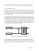
XR315IN-510 12V DC Output = LED Up & Down Inputs = Momentary Program: Amplifier Signal Processing Mixer 1234567 Figure 1 XR315 Receptacles Location 1 Location 3 Use an LED and 1K, ¼W resistor at each location Location 2 Single-Unit System Controlled by Momentary Switches
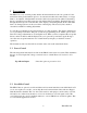
XR315IN-510 Aux Output = Confirm Up & Down Inputs = Latching Program: Amplifier Signal Processing Mixer Figure 2 1234567 XR315 Receptacles Low Voltage Contact Closure Controller Confirmation Feedback Single-Unit System Controlled by Central Controller
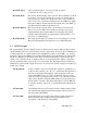
XR315IN-510 Aux Delay Off = [Set as Needed] Aux Delay On = [Set as Needed] Aux Output = A, B or C 12v DC Output = LED Up & Down Inputs = Momentary Program: 1234567 XR315 Receptacles Momentary Switch Figure 3 LED and 1K, 1/4W Resistor Confirmation (If Required) SX1120-RT A-On Switched 1 2 3 4 5 6 7 Expanded System Using Aux Relay
XR315IN-510 Aux Output = Confirm 12V Delay Off = [Set as Needed] 12V Delay On = [Set as Needed] 12v DC Output = A, B or C Up & Down Inputs = Momentary Program: 1234567 XR315 Receptacles Momentary Switch Confirmation (If Required) Figure 4 SX1120-RT A-On Switched 1 2 3 4 5 6 7 Expanded System Using 12V DC Output
XR315IN-510 1234567 1234567 Aux Output = Gang 12V DC Output = LED Figure 5 Up & Down Inputs = Latching Up & Down Inputs = One Mom.
XR315IN-510 Over-Ride Input = 5-30 VDC Over-Ride Func = Pass-Thru 12V DC Output = Cascade Aux Output = Cascade Over-Ride Input = 5-30 VDC Over-Ride Func = Master 12V DC Output = LED Aux Output = Cascade Figure 6 Up & Down Inputs = Latching Program: 1234567 XR315 Receptacles Up & Down Inputs = One Mom.
7 Troubleshooting Initial Check Whenever power is applied to the XR315 the LCD display should be illuminated and should show two lines of text as follows: OFF or ON 120V 0A (or whatever the actual line voltage and load current are) Power: (or whatever the actual power calculation is) 0W If the first line of the display does not show “OFF” or “ON” the unit is in programming mode and therefore the receptacles will not turn on.
There are two likely causes for this: One cause is a Down input that is on all the time and overriding the power up function. Check the down input with a meter. The other cause is that the Over-Ride Func menu item has been set to Master when the unit is not actually connected to another XR315 and is in cascade mode. Change this menu item to Disable. The unit will not go into programming mode You must power down the unit first before you can get into the programming mode.
9 Specifications Operational Voltage Range: 90 to 150 Volts AC Current rating: 15 Amps Power Rating: 1,800 Watts Maximum Load Inrush Energy: 1400 Joules total during power-up Surge Let-through Voltage: Zero let-through Voltage for a 6000 Volt surge Meets Federal Guidelines: Grade A, Class 1, Mode 1 (CID A-A-55818) EMI/RFI Filter, Normal Mode: 40 dB @ 100 KHz, 50dB @ 300 KHz, 50 dB @ 3 MHz, 50 dB @ 30 MHz (50 Ohm load) EMI/RFI Filter, Common Mode: 18dB @ 300 KHz, 30 dB @ 1 MHz, 50 dB @ 5 MHz