
User Guide


Table Of Contents
SureCall, Inc | 1-888-365-6283 | support@surecall.com | www.surecall.com SureCall, Inc | 1-888-365-6283 | support@surecall.com | www.surecall.com
13
12
Step 4: Connect to Power and Turn On
Connect the AC power cord to the booster and plug into a 110V AC power outlet. Once the booster has been
completely assembled, turn the booster’s power switch to ON.
Note: If the Power LED does not turn ON or the Alert LEDs continue to ash, see the ”Troubleshooting” on page 14
section.
Note: This booster is rated for 5-15V input voltage. DO NOT use the booster with a higher voltage power supply. This can damage the booster, cause personal injury,
and void your warranty.
Step 5: Congure Gain Settings If Needed
Place a call in the room where the inside antenna is located to conrm that your phone is receiving a boosted
signal.
Note: Bars are not always a reliable measure of signal. The best way to conrm signal coverage is the ability to
place and hold a call.
Booster gain dials or switches should always be at maximum level unless the control light for a specic
frequency band is ashing red or ashing red-yellow. In either case, only reduce gain dials if the recommended
actions found in “LED Indicators” on page 13 do not resolve the issue.
It is best to avoid turning the gain dial below 40 dB as this could cause affected frequency band to stop
amplifying.
IF YOU WANT TO IMPROVE PERFORMANCE
• Identify a location outside that receives a stronger signal and move the outside antenna to that location
(higher is usually better.
• Increase the distance between the booster and outside antenna - vertical separation is better than
horizontal.
• If using an omni outside antenna, upgrade to a directional yagi antenna that can be aimed toward your
closest tower.
Installation
LED Indicators
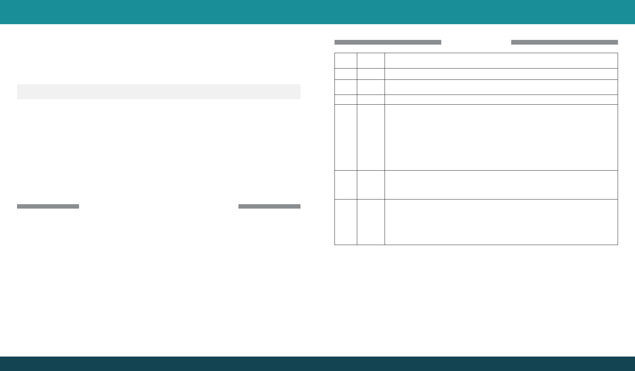
LED INDICATORS
LED
Color
LED
Condition
Resolution
OFF This is part of normal operation. Light is off while band is active.
Yellow Solid
This is part of normal operation. Indicates that the frequency band is not being used. After a period of
time, if there’s no activity, that band will go into sleep mode.
Yellow Flashing
This is part of normal operation. Indicates that the Automatic Gain Control (AGC) is self-adjusting.
Red Flashing Indicates that the booster is receiving too much signal which could cause the affected band to
automatically turn off. When this happens:
1. For kits using an OMNI outside antenna, relocate the outside antenna to a location where the
signal is weaker.
2. For kits using a YAGI outside antenna, turn the antenna in short increments away from the signal
source.
3. Increase the separation between antennas (additional vertical separation works best).
4. Add an inline attenuator to the cable coming into the outside port of the booster.
5. Though not desirable as amplication will not be optimum, lower the dB gain setting in small
increments until the light turns off or ashes yellow.
Red Solid The frequency band is off.
If a red light has been ashing for an extended time due to too much signal, that frequency band will
display a solid red light indicating that the circuitry for that frequency band has been turned off.
This can also happen when the gain dial for a frequency band has been turned all the way down.
Yellow/
Red
Alternately
Flashing
Self-oscillation has been detected and to prevent it, one or more of the frequency bands have shut
down.
If this happens: First, try increasing the separation between the inside and outside antennas. If your
booster kit uses directional antennas (example: outside Yagi antenna and inside panel antenna),
ensure that they are facing away from one another.
If condition continues, lower the dB gain setting in small increments until the light turns off or ashes
yellow.