Input Module INSTALLATION GUIDE Version 1.02 English EN 101.00.IM-120 V1.
CONTENTS Safety information 2 Instructional icons 2 Introduction 4 Components 4 Accessory 5 Name and function of each part 6 Installation example 8 Product Specifications 18 FCC compliance information 20 Appendices 21 Disclaimers 21 Copyright Notice 21 Open Source License 21 MIT Open Source License Installation 9 Power Connection 9 RS-485 Connection 10 Relay Connection 11 Supervised Input Connection 12 Tamper Connection 13 Using the Input Module with the enclosure 13
Safety information Please read this safety instructions before you use the product to prevent injury to yourself and others and to prevent property damage. The term 'product' in this manual refers to the product and any items provided with the product. Warning: This symbol indicates situations that could result in death or severe injury. Caution: This symbol indicates situations that may result in moderate injury or property damage. Note: This symbol indicates notes or additional information.
Safety information Caution Installation Do not install the product under direct sunlight or UV light. • This may result in product damage, malfunction, discoloration, or deformation. Do not install the power supply cable in a location where people pass by. • This may result in injury or product damage. Do not install the product near magnetic objects, such as a magnet, TV, monitor (especially CRT), or speaker. • The product may malfunction.
Introduction Introduction Components 160 190 80 90 80 IM-120 Input Module Drilling Template (IM-120) Input Module Open Source Software 201.00.IM-120 V*.*** MIT License E Quick Guide Fixing Screw x12 306.01 V*.*** Open Source Software Guide Spacer x6 Components may vary according to the installation environment.
Introduction Accessory You can use the Input Module with the enclosure (ENCR-10). The enclosure is sold separately, and you can install two Input Modules in one enclosure. The enclosure includes a power status LED board, power distribution board, power supply, and tamper. To learn how to install the Input Module in the enclosure, refer to Using the Input Module with the enclosure. ENCR-10 • There is no optimal height for installing ENCR-10 on the wall.
Introduction Name and function of each part 1 5 2 12 3 11 4 10 5 9 6 8 7 No.
Introduction LED Indicator You can check the status of the device by the color of the LED indicator.
Introduction Installation example The Input Module provides instant relay behavior by connecting to BioStar 2 for detected inputs in real-time and it operates a relay or saves logs for detected inputs while it is disconnected from the master device. The Input Module supports 12 channel supervised input, 2 channel relay, 2 channel AUX input, and 1 channel tamper input to detect status, such as 1 channel RS-485, disconnection, short, on, or off for networking with the master device.
Installation • To learn how to install the Input Module in the enclosure, refer to Using the Input Module with the enclosure. Fix a spacer on the position to mount Input Module using a fixing screw. Fix the product on top of the fixed spacer firmly using a fixing screw. Power Connection DC Power 12 VDC or 24 VDC GND • Make sure to use separate power for the access control device and Input Module. • Use the correct power specifications (12 VDC, 130 mA or 24 VDC, 82 mA).
Installation RS-485 Connection You can connect the Input Module to a master device. • Use an AWG24 twisted pair with less than 1.2 km in length for the RS-485 cable. • If connecting with a RS-485 daisy chain, connect the termination resistor (120 Ω) to both ends of the daisy chain connection. If connected to the middle line, the signal level becomes smaller and the communication performance will deteriorate. Make sure to connect it to both ends of the daisy chain connection.
Installation Relay Connection The relay of the Input Module can control door locks and alarms. Connect the relay as NC (Normally Closed) or NO (Normally Open) by referring to the installation guide of the connection device. DC Power Alarm Dead bolt / Door strike • Fail Safe Lock: In order to use the Fail Safe Lock, connect the NC relay as shown in the figure below. There is normally a current flowing through the relay for the Fail Safe Lock.
Installation • Connect a diode to both ends of the power input as shown in the figure below when installing a deadbolt or a door strike. Make sure to connect the Cathode (direction to the stripe) to the + part of the power while paying attention to the direction of the diode. • Do not connect the relay of the Input Module in duplicate to the device connected to the relay port of the master device.
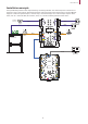
Installation Tamper Connection If Input Module is detached from the installed location due to an external factor, it can trigger an alarm or save an event log. Tamper Using the Input Module with the enclosure The Input Module can be installed inside the enclosure (ENCR-10) for physical and electrical protection. The enclosure includes a power status LED board, power distribution board, power supply, and tamper. The enclosure is sold separately.
Installation • The battery is sold separately. • If the dimension of the backup battery is larger than the recommended specification, it may not be able to be mounted in the enclosure or the enclosure may not close after it is mounted. Also, if the shape and dimension of the terminals are different, the battery cannot be connected using the cable provided. (Unit: mm) 4.75 Terminal 6.6 43 151 99 Backup Battery 94 0.8 6.
Installation 2 After positioning the Input Module in the enclosure, fix it with the fixing screws. • There is no optimal height for installing ENCR-10 on the wall. Install it to a safe and convenient location for you to use. • Fixing screws for the enclosure, the device and the power supply cable are included in the ENCR-10 package. Use each screw correctly by following the details below.
Installation Power and AUX Input Connection You can connect an Uninterruptible Power Supply (UPS) to prevent power failure. And a power failure detector or a dry contact output can be connected to the AUX IN terminal. • Make sure to use separate power for the access control device and Input Module. • Use the correct power specifications (12 VDC, 130 mA or 24 VDC, 82 mA).
Installation Tamper Connection If Input Module is detached from the installed location due to an external factor, it can trigger an alarm or save an event log. • For more information, contact the Suprema technical support team (support.supremainc.com).
Product Specifications Feature Model IM-120 CPU Cortex M3 72 MHz Memory 512 KB Flash + 64 KB SRAM LED General Interface Capacity • • • • • • • • • Multi-color Power - 1 Status - 1 RS-485 TX - 1 RS-485 RX - 1 Supervised Input - 12 Relay - 2 AUX IN - 2 Tamper - 1 Operating Temperature -20°C–60°C Storage Temperature -40°C–70°C Operating Humidity 0 %–95 %, non-condensing Storage Humidity 0 %–95 %, non-condensing Dimension (W x H x D) 90 mm x 190 mm x 21 mm Weight 203 g Certificates CE,
Product Specifications Dimensions (Unit: mm) * The tolerance is ±0.3 mm.
FCC compliance information Operation is subject to the following two conditions: (1) This device may not cause harmful interference, and (2) This device must accept any interference received, including interference that may cause undesired operation. • This equipment has been tested and found to comply with the limits for a Class A digital device, pursuant to part 15 of the FCC Rules. These limits are designed to provide reasonable protection against harmful interference in a commercial installation.
Appendices Disclaimers • The right to use is acknowledged only for Suprema products included in the terms and conditions of use or sale for such products guaranteed by Suprema. No license, express or implied, by estoppel or otherwise, to any intellectual property is granted by this document.
Appendices MIT Open Source License Permission is hereby granted, free of charge, to any person obtaining a copy of this software and associated documentation files (the "Software"), to deal in the Software without restriction, including without limitation the rights to use, copy, modify, merge, publish, distribute, sublicense, and/or sell copies of the Software, and to permit persons to whom the Software is furnished to do so, subject to the following conditions: The above copyright notice and this permiss
Suprema Inc. 17F Parkview Tower, 248, Jeongjail-ro, Bundang-gu, Seongnam-si, Gyeonggi-do, 13554, Rep. of KOREA Tel: +82 31 783 4502 | Fax: +82 31 783 4503 | Inquiry: sales_sys@supremainc.com For more information about Suprema’s global branch offices, visit the webpage below by scanning the QR code. https://supremainc.com/en/about/global-office.asp © 2022 Suprema Inc. Suprema and identifying product names and numbers herein are registered trade marks of Suprema, Inc.